Introduction
Engine blocks rank among the most challenging components in precision machining. They demand complex multi-surface geometry, ultra-tight tolerances, and perfect alignment across dozens of critical features — requirements that push traditional 3-axis machining to its limits. A V8 engine block, for example, must maintain main bearing bore alignment within 0.0002 inches while keeping deck surfaces flat to within 0.001 inch per 3-inch span. Even slight misalignment causes premature bearing wear, head gasket failure, and accelerated mechanical failure across the entire drivetrain.
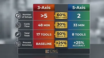
5-axis CNC machining has become the industry standard for high-performance engine block work because it approaches complex features from virtually any angle in a single setup. This eliminates the cumulative repositioning errors that plague conventional multi-setup operations. According to DMG Mori's 2024 white paper, 5-axis machining reduces setups by 60% (from >5 to 2), cuts cycle time by 30%, and improves process accuracy by 25%.
This guide walks through everything you need to evaluate and execute 5-axis engine block machining — from setup strategy and critical operations to material selection, common failure points, and inspection practices.
Key Takeaways
- 5-axis CNC consolidates deck milling, cylinder boring, main bearing alignment, and lifter bore correction into one setup, reducing repositioning errors and cutting cycle time by 30–50%
- Main bearing bore alignment requires .0002-inch concentricity; deck surfaces demand .001-inch flatness per 3-inch span — both achievable only through single-datum machining that eliminates cumulative repositioning error
- Aluminum blocks (21.4 µm/m/°C CTE) require active thermal management versus cast iron (9.9 µm/m/°C), using controlled coolant temperature and semi-finishing passes before final cuts
- CAM simulation tools prevent costly collisions in complex 5-axis tool paths before cutting begins
- Post-machining CMM inspection verifies bore roundness, deck flatness, and bearing alignment before finishing steps like bead blasting and anodizing
Why 5-Axis CNC Machining Outperforms 3-Axis for Engine Blocks
The Fundamental Axis Difference
3-axis CNC machines move the cutting tool along X, Y, and Z linear axes only. To access different faces of an engine block — the deck surface, cylinder bores, main bearing tunnels, and lifter bores — the workpiece must be manually unclamped, repositioned, and re-fixtured. Each repositioning introduces new datum registration error that compounds across features.
5-axis CNC adds rotational A and B axes, allowing continuous multi-angle cutting without removing the part from the fixture. The tool approaches the workpiece from virtually any orientation while maintaining a single datum reference established at setup.
For engine blocks — where main bearing bores, cylinder banks, deck surfaces, and lifter bores must maintain precise geometric relationships — this single-setup advantage directly translates to geometric accuracy.
Quantified Performance Gains
DMG Mori's 2024 comparison documents the performance gap between 3-axis and 5-axis machining:
| Metric | 3-Axis | 5-Axis | Improvement |
|---|---|---|---|
| Number of setups | >5 | 2 | 60% reduction |
| Cycle time (min) | 48 | 33 | 30% reduction |
| Total tools required | 17 | 8 | 50% reduction |
| Process accuracy | Baseline | +25% | Measurable gain |
DMG Mori achieves form and positional tolerances of <3 micrometers through 5-sided machining in one clamping, with measuring repeatability of 0.8 micrometers on their systems.
Modern Machine Shop reported 5-axis CAM strategies enabled 50% machining time reduction by consolidating operations to one setup, with 30-40% programming time savings. Evans Industries achieved cycle time reduction from 23 hours to 13 hours per part (43.5%).
3-Axis vs. 4-Axis vs. 5-Axis Comparison
Those performance numbers reflect a real capability gap across axis configurations:
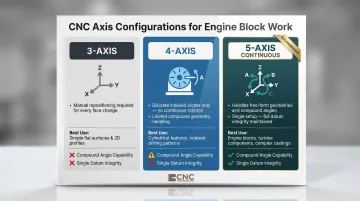
- 3-axis: Works for simple flat surfaces like basic deck milling, but every feature orientation change requires manual repositioning
- 4-axis (indexed): A rotary table locks at preset angles, reducing re-fixturing — but discrete indexing stops prevent it from handling compound-angle or free-form geometries
- 5-axis continuous: Handles fully free-form geometries found in performance and racing engine blocks — angled lifter bores, compound-angle oil passages, and sculpted coolant galleries — all while maintaining datum integrity
Consolidated Operations Reduce Total Cycle Time
5-axis machining centers consolidate operations that historically required multiple machines: a milling machine for deck surfaces, a boring machine for cylinders, a separate align-honing fixture for main bearing bores, and specialty accurizing setups for lifter bores.
Modern 5-axis centers complete tool changes in as little as 2.9 seconds (Grob G550 specification), fast enough that sequential operations run without meaningful interruption between passes.
Realizing these advantages depends heavily on the quality of the underlying CNC programs. 5-axis tool paths must account for tool orientation, collision avoidance, and cutting sequence simultaneously — complexity that demands experienced programmers who understand both the machine's kinematics and the engine block's geometric requirements. CNC Programming Solutions develops these multi-axis programs for shops running 5-axis centers, handling the programming side so machinists can focus on running parts.
Key 5-Axis CNC Machining Operations on Engine Blocks
A 5-axis machining center executes most block operations sequentially without repositioning, with probe and datum reference set once at the start of the job.
Deck Surface Milling
Deck milling flattens each bank of the engine block to be perfectly parallel to the crankshaft centerline and equidistant from it — critical for head gasket sealing and consistent compression ratios.
The Process:
- The CNC probe maps existing deck height at multiple points
- The program calculates exact material removal needed
- The cutter machines both decks to specification
Stock V8 blocks allow .004 inches lengthwise out-of-flat; performance targets tighten to .002 inches with .001 inch per 3-inch span. Meeting these tolerances demands probing before milling to account for casting variation.
Cutter Choices by Material:
- Cast iron: CBN (cubic boron nitride) for high-speed finishing; coated carbide for roughing
- Aluminum: PCD (polycrystalline diamond) inserts
With 5-axis capability, both decks on a V-type block can be cut sequentially by rotating the block on the A-axis, ensuring both banks achieve perfect angular and height symmetry relative to the crank centerline — a result difficult to guarantee with conventional resurfacing machines.
Surface Finish Requirements:
| Gasket Type | Ra (microinches) | Application |
|---|---|---|
| Stock MLS | 30 or less | OEM rebuilds |
| Performance MLS | 20-30 (recommended) | High-performance engines |
| Conventional Composite | 60-80 (ideal) | Standard applications |
Cylinder Boring and Honing
Cylinder boring begins with the CNC machine using probe data to locate the existing bore centerline. The programmer then decides whether to follow OEM blueprint specs or the existing centerline before the boring head removes material to the target diameter — slightly undersized to leave stock for honing. A torque plate bolts to the block during boring to simulate head bolt clamping forces and prevent cylinder distortion.
Torque plate boring is essential for closed-deck blocks, where head bolt holes connect directly to cylinder walls. Without it, bores machined round in a free state become out-of-round when the head is torqued on, compromising ring seal.
Honing is the final sizing step, typically performed on a dedicated honing machine after 5-axis boring. Abrasive stones produce the crosshatch pattern of 22 to 32 degrees from horizontal, uniform in both directions. Performance applications may use 30-45 degrees. This pattern retains oil for lubrication while promoting uniform piston ring seating during break-in.
Main Bearing Bore Alignment and Cam Tunnel Machining
Align boring corrects or resizes main bearing bores so all are concentric and aligned to the crank centerline. The maximum allowable alignment tolerance is .0002 inches (two tenths of a thousandth).
The process:
- A precision fixture bar passes through the main bore
- The probe zeros all axes off this reference
- The program machines each bore to specification in sequence
Machining main bearing bores, cam tunnels, and deck surfaces in a single clamping eliminates the re-fixturing error that would otherwise compromise the geometric relationship between these features — one of the clearest productivity advantages of 5-axis setups.
For cam tunnel machining, a centering fixture self-locates within the tunnel and provides the reference surface for the probe to establish the cam-to-crank relationship. The program then machines or hones the tunnel to correct alignment, ensuring proper camshaft bearing fitment and valve timing accuracy.
Lifter Bore Correction and Accurizing
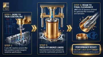
OEM production blocks often have lifter bore centerlines that deviate from their designed blueprint positions — a tolerance stack-up that costs measurable power. A 2017 Engine Builder Magazine study found that correcting misaligned lifter bores yielded +20.5 hp and +20.5 lb-ft torque, while improving oil pressure by 5 psi and reducing EGT spread from 80°F to 60°F.
The Correction Process:
- The 5-axis machine bores lifter bores to true centerline positions
- Bronze liners are press-fit into the enlarged bores
- Liners are reamed to final oil clearance (.0017 inches typical)
Machining all 16 lifter bores on a V8 takes 10-12 minutes on a CNC center versus much longer with manual methods. The performance gain comes from consistent valve timing events across all cylinders, eliminating the timing flutter caused by lifter-to-cam lobe misalignment.
Materials, Tolerances, and Fixturing Essentials
Cast Iron vs. Aluminum Alloys
| Property | Gray Cast Iron (Class 40) | Aluminum A356-T6 | Source |
|---|---|---|---|
| Brinell Hardness | 183-234 HB | 70-105 HB | MatWeb |
| Density | 7.15 g/cc | 2.67 g/cc | MatWeb |
| CTE (20-100°C) | 9.9-12.1 µm/m/°C | 21.4 µm/m/°C | MatWeb |
| Thermal Conductivity | 53.3 W/m-K | 151 W/m-K | MatWeb |
| Recommended Tooling | CBN, ceramic | PCD | Sandvik |
Cast iron is harder, dimensionally stable, and uses CBN tooling at high speeds with dry cutting. Its lower CTE provides inherently more dimensional stability during machining.
Aluminum alloys (A356-T6, 319-T5, or billet 7075) are lighter and conduct heat 3x faster than cast iron, but have a coefficient of expansion more than 2x that of cast iron. This demands careful thermal management: coolant temperature control, stabilization periods before final cuts, and measurement at controlled reference temperatures.
A 10°C temperature rise on an aluminum block with a 400 mm bore span produces approximately 85 micrometers (0.0033 inches) of linear expansion. The same rise on cast iron produces only 40-48 micrometers.
Tolerance Levels in Precision Engine Block Work
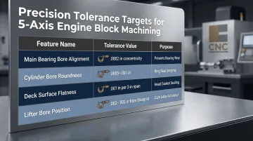
| Feature | Typical Tolerance Range | Purpose |
|---|---|---|
| Main bearing bore alignment | .0002 inches concentricity | Prevents bearing wear, crank fatigue |
| Cylinder bore roundness | .0005-.001 inches | Ring seal integrity |
| Deck surface flatness | .001 inch per 3-inch span | Head gasket sealing |
| Lifter bore position | .002-.003 inches from blueprint | Cam lobe contact accuracy |
These tight tolerances drive the need for single-datum machining. Every re-fixturing event introduces error that compounds across interdependent features.
Fixturing Strategy as a Core Engineering Challenge
Custom fixture design requirements:
- Distribute clamp forces evenly across structural areas, never thin-walled sections
- Position fixtures to allow full 5-axis tool access from all required angles without collision risk
- Hold crank centerline and cam tunnel axis as consistent datum references across every operation
A poorly designed fixture causes datum drift that compounds into assembly misalignment. The fixture bar through the main bore establishes the primary datum; the cam tunnel centering fixture establishes the secondary datum. All subsequent machining operations reference these two datums.
Thermal Management During Machining
Cutting generates heat that causes aluminum and even cast iron to expand, introducing dimensional inaccuracy. Control methods include:
- Optimized roughing strategies that balance material removal rates
- Semi-finishing passes to relieve residual stress before finishing cuts
- Proper coolant flow management and temperature monitoring
- Spindle speed and feed rate selection that accounts for material thermal sensitivity
For aluminum, allow thermal stabilization periods between roughing and finishing operations.
Common Challenges in 5-Axis Engine Block Machining
Maintaining Alignment Across Large, Complex Workpieces
Engine blocks are large, irregularly shaped castings where even small errors in datum setup compound across multiple features. Misaligned main bores, cam tunnels, or lifter bores cause premature bearing wear, camshaft failure, and reduced engine life.
Solution: Probe at multiple reference points before cutting, and implement mid-operation verification checks. The 5-axis advantage is that once the datum is established, every feature machines relative to that single reference.
Thin-Wall Deflection and Material Variability
Performance engine blocks often have thin walls between coolant passages and cylinder bores that deflect under cutting forces, causing out-of-round bores.
Mitigation approaches:
- Lighter finishing passes with reduced radial engagement
- Higher spindle speeds with lower chip loads
- Strategic fixturing to support thin sections from behind
Material variability adds another layer of risk. Aftermarket or used blocks often carry inconsistent properties — porosity, prior repairs, sand inclusions — that affect tool wear unpredictably. In cast iron specifically, abrasive flank wear from SiC and sand inclusions is the primary tool failure mode.
Operator Skill and Programming Complexity
5-axis engine block machining requires multi-stage CAM programming to define tool paths, tool orientations, cutting sequences, and collision-avoidance for a complex workpiece. Errors in programming can scrap an expensive block.
Essential safeguards:
- Use experienced CNC programmers familiar with 5-axis kinematics
- Verify programs with simulation software before cutting
- Simulate with tools like hyperMILL Virtual Machining Center or Vericut for NC-code-level collision checking and real-time shop floor data connectivity
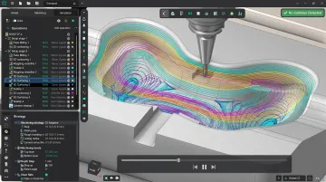
With long cycle times and expensive workpieces at stake, always run full simulation verification before the first cut.
Quality Control and Post-Machining Finishing
CMM Inspection as the Verification Standard
Coordinate Measuring Machine inspection verifies 5-axis engine block work with micron-level precision. CMM checks:
- Main bearing bore concentricity and diameter
- Cylinder bore roundness, taper, and cylindricity
- Deck surface flatness and perpendicularity to crank centerline
- Lifter bore position relative to blueprint
- Oil gallery intersections
All critical dimensions should be documented in a traceable inspection report per ASME B89.7.2 dimensional measurement planning standards.
Renishaw offers two primary probe technologies for this work. Kinematic touch-trigger probes (OMP40-2, OMP60) handle general workpiece setup, while strain gauge probes with RENGAGE technology (MP250, OMP400) deliver high-precision 3D surface measurement with reduced contact force.
Post-Machining Cleaning and Surface Finish Verification
After machining, all metal chips, coolant residues, and abrasive particles must be thoroughly removed from oil passages, threaded holes, and coolant galleries to prevent assembly contamination. Once the block is clean, a final profilometer measurement confirms that cylinder wall and deck surface roughness meets specification — because surface geometry matters as much as cleanliness.
Surface waviness — low-frequency undulations — is the primary cause of gasket sealing failure, not Ra alone. Any machining stripe wider than .030 inches classifies as waviness.
Post-Machining Finishing Services
Once dimensional verification is complete, finishing processes prepare the block for assembly or delivery. Common services include:
- Bead blasting — cleans and textures external surfaces, removing oxidation and contaminants while improving appearance
- Vibratory deburring — clears burrs from machined edges and passages, improving fit and safety during assembly
Anodizing (MIL-A-8625 Type III Hardcoat):
| Coating Type | Thickness Range | Hardness | Key Attribute |
|---|---|---|---|
| Type I (Chromic Acid) | ~0.0001 inches | Low | Thin, corrosion protection |
| Type II (Sulfuric Acid) | 0.0002-0.0006 inches | Moderate | Decorative, dyeable |
| Type III (Hardcoat) | 0.0005-0.0030 inches | 60-70 Rc | Maximum abrasion resistance |
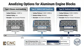
Type III hardcoat dimensional change: 50% penetrates the surface, 50% builds up — a 0.002-inch coating produces a 0.001-inch dimensional increase per surface. Dimensional planning must account for this buildup.
- Powder coating — delivers durable protective and decorative finishes for external surfaces, guarding against corrosion and environmental exposure
CNC Programming Solutions offers all of these finishing services in-house, so engine block work moves from machining to final finish without leaving the production workflow.
Frequently Asked Questions
Can you CNC an engine block?
Yes, CNC machining is the standard method for both manufacturing new engine blocks and rebuilding existing ones. 5-axis CNC centers handle deck milling, cylinder boring, align honing, and lifter bore correction in a single setup, maintaining datum integrity across all features.
What are the limitations of 5-axis CNC?
5-axis CNC comes with real trade-offs to weigh before committing:
- High machine and programming costs compared to conventional equipment
- Requires expert programmers to generate collision-free 5-axis tool paths
- Longer initial setup times for datum establishment
- Some final operations like cylinder honing still require dedicated equipment
What tolerances can 5-axis CNC achieve on engine blocks?
5-axis CNC achieves micron-level accuracy on critical features. Typical tolerances include .0002 inches for main bearing bore alignment, .0005-.001 inches for cylinder bore roundness, and .001 inch per 3-inch span for deck surface flatness in high-performance applications.
How does 5-axis CNC reduce setup time compared to conventional machining?
5-axis CNC consolidates deck milling, boring, cam tunnel alignment, and lifter bore correction onto one machine. With tool changes taking only 2.9 seconds on modern centers, it eliminates the hours lost repositioning the block across multiple machines and specialty fixtures.
What materials are most commonly used in 5-axis CNC engine block machining?
The two dominant materials are cast iron and aluminum alloys:
- Cast iron — traditional, dimensionally stable, machined with CBN tooling
- Aluminum alloys (A356-T6, 7075 billet) — lighter, favored in performance and racing builds, but require careful thermal and distortion management
When should a shop choose 5-axis over 3-axis CNC for engine block work?
5-axis is the right call in these situations:
- The block needs accurizing — correcting bore centerlines back to blueprint spec
- Geometry includes compound angles or free-form surfaces
- Tight tolerances are required across multiple faces simultaneously
- Minimizing repositioning errors and maximizing throughput are priorities
About CNC Programming Solutions
CNC Programming Solutions provides CNC programming and contract machining services for precision components, including multi-axis milling and lathe work. We also handle finishing — vibe deburring, bead blasting, anodizing, and powder coating — so you get a complete solution from a single source.
Contact us at 405-714-3714 or cncsolutions22@gmail.com to discuss your precision machining requirements.