Key Takeaways
- CNC lathes rotate the workpiece while a stationary cutting tool shapes it—controlled by G-code programming
- Seven core components work together to enable precise cutting: headstock, spindle, chuck, turret, tailstock, carriage, and machine bed
- Common operations: turning, facing, threading, boring, drilling, grooving, and knurling
- Axis configurations range from basic 2-axis lathes to complex 5+ axis turning centers with live tooling
- Compared to manual lathes, CNC lathes produce tighter tolerances and significantly higher throughput—making them the standard for production machining
Key Parts of a CNC Lathe and Their Functions
Understanding CNC lathe components helps manufacturers select the right machine and troubleshoot production issues. Each part plays a specific role in holding, rotating, or cutting the workpiece.
Headstock and Main Spindle
The headstock houses the main motor and spindle—the "engine" of the lathe. Mounted in a fixed position (typically on the left end), the headstock rotates the workpiece through the chuck while maintaining precise coaxial alignment with the tailstock. The spindle speed range directly impacts the machine's ability to handle different materials and part sizes, with modern lathes reaching 4,500+ RPM for smaller-diameter work.
Chuck and Collet
The chuck is the clamping device that grips the workpiece during rotation. Two main types serve different purposes:
- 3-jaw (self-centering): Automatically centers round or hexagonal stock, enabling faster setup for symmetrical parts
- 4-jaw (independent): Each jaw adjusts separately, ideal for irregular shapes or off-center work requiring precise positioning
For higher-precision work on smaller-diameter parts (typically under 42mm or 1-5/8"), collets offer superior accuracy. High-grade collets deliver runout below 0.005mm when properly installed, critical for tight-tolerance applications.
Tailstock and Carriage
Once the workpiece is secured in the chuck or collet, the tailstock supports its opposite end, preventing deflection during cutting that would compromise dimensional accuracy. It holds a lathe center in its ram for turning or facing operations, or accepts drilling tools directly through its internal Morse taper.
The carriage holds and moves the cutting tool along the workpiece. Its four components — saddle, apron, compound slide, and cross slide — enable precise longitudinal (Z-axis) and cross-cutting (X-axis) motion.
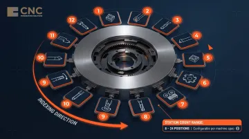
Tool Turret
The turret is the rotating tool-holding station that allows multiple tools to be pre-loaded and indexed automatically. CNC lathe turrets typically contain 8 to 24 tool stations, enabling complex multi-step operations — drilling, turning, and grooving — within a single setup. Higher station counts reduce cycle time on parts requiring many tool changes. For reference, a 12-station turret handles most shaft and sleeve work, while 16–24 stations suit complex prismatic parts or jobs requiring both live and static tooling.
Machine Bed and Guideway
The bed is the rigid base on which all components mount, usually made of cast iron for vibration damping and dimensional stability. The guideways (ways) control the precision movement of the carriage along the bed. Two main designs exist:
Box ways use hardened, ground sliding surfaces that maximize contact area between moving components. That broad contact makes them more forgiving under shock loads and heavy interrupted cuts — the reason many heavy-duty turning centers still use them despite requiring constant lubrication.
Linear guides replace sliding surfaces with recirculating ball or roller bearings on rails. The result is lower friction, faster rapid traverse speeds, and less heat buildup over long runs. For high-speed finishing work or lights-out production, linear guides typically hold accuracy better over time.
The practical choice comes down to the work: box ways for roughing and heavy stock removal, linear guides for high-speed finishing and tight-tolerance production runs.
How a CNC Lathe Machine Works
Unlike a CNC mill where the tool moves around a stationary workpiece, in a CNC lathe the workpiece rotates at high speed while the cutting tool remains stationary on the turret. This rotation-based material removal is called "turning," which is why CNC lathes are also known as CNC turning machines.
Programming and Setup
A machinist or CNC programmer writes G-code (using a machine controller directly or via CAD/CAM software) that defines spindle speed, feed rate, depth of cut, and tool path. G-code (Geometric Code) is the primary language used to control CNC machines, with approximately 70 standard codes ranging from G00 to G99.
Operational Sequence
- Raw material is clamped in the chuck
- Program is loaded and dry-run verified
- Spindle accelerates to programmed RPM
- Turret indexes to the first tool
- Tool engages the rotating workpiece along programmed X (radial) and Z (longitudinal) axes
- Subsequent tools are automatically indexed for multi-step operations
How Axis Count Determines What the Machine Can Do
The operational sequence above describes a standard 2-axis setup, but axis count is what separates a basic lathe from a full turning center. A 2-axis lathe moves the tool in X (cross) and Z (longitudinal) directions only, handling standard turning, facing, and drilling operations. Adding a C-axis enables rotational positioning of the spindle for live tooling — milling and drilling off-center features without re-fixturing the part. Turning centers with C-axis, Y-axis, and driven tools can perform turning, milling, drilling, and tapping operations in one setup.
CNC Lathe Operations and Processes
CNC lathes rank among the most versatile subtractive machining tools available—a single setup can execute a sequence of distinct operations, each removing material differently to achieve the final part geometry.
Turning and Facing
Turning is the foundational operation: the cutting tool moves parallel to the workpiece axis (Z direction) to reduce the outer diameter (OD) and achieve the target cylindrical profile. Material removal occurs as the rotating workpiece contacts the stationary cutting edge.
Facing moves the tool perpendicular to the axis (X direction) to create a flat, square end surface on the workpiece, reducing the workpiece length to exact size.
Threading, Grooving, and Parting
Threading follows a precise helical path along the OD or ID to cut external or internal threads to a specified pitch and length—critical for fasteners, pipe fittings, and threaded connections.
Grooving cuts a narrow channel of specific width and depth into the surface. Common applications include:
- O-ring grooves for sealing
- Snap ring seats for retaining components
- Undercuts for assembly clearance
Parting uses a narrow tool that plunges radially into the workpiece to cut off the finished part from bar stock.
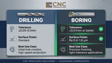
Boring and Drilling
Drilling creates holes at the center of the rotating workpiece using a drill bit mounted in the turret. Boring follows drilling to enlarge the hole to a precise diameter and achieve tight tolerances or internal features like tapers, steps, and contours.
CNC boring achieves tolerances of ±0.01mm or better with surface finish Ra 0.4-1.6 µm, compared to drilling's typical ±0.05-0.1mm tolerance. Boring is preferred when hole accuracy exceeds what drilling alone can achieve.
Reaming, Tapping, and Knurling
Three additional operations handle fine finishing and surface detailing on the lathe:
- Reaming — removes a small, precise amount of material from a drilled hole to achieve a highly accurate diameter and smooth internal finish
- Tapping — cuts internal threads in a pre-drilled hole for fastener assembly
- Knurling — uses a patterned roller to press a textured pattern into the workpiece surface, commonly for grip surfaces on knobs, handles, and tool shanks
Once cutting operations are complete, parts often require post-machining finishing to meet final specifications. Processes like bead blasting, vibratory deburring, anodizing, and powder coating address surface quality, corrosion resistance, and cosmetic requirements—areas where CNC Programming Solutions provides dedicated finishing services alongside its lathe and milling work.
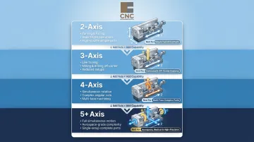
Types of CNC Lathes by Axis Configuration
The number of axes determines the machine's capability: more axes mean more operations can be completed in a single setup, reducing handling time and improving part accuracy.
Each additional axis expands what a single setup can accomplish:
| Configuration | Capabilities | Best For |
|---|---|---|
| 2-Axis (X/Z) | OD/ID turning, facing, drilling at center, threading | High-volume cylindrical parts, simple geometries |
| 3-Axis (adds C) | Standard milling, off-axis drilling, tapping with live tooling | Parts requiring both turning and milling features |
| 4-Axis (adds Y) | Off-center operations, vertical tool movement, complex contouring | Asymmetric features, complex part geometries |
| 5+ Axis | Sub-spindle, dual-tool simultaneous cutting, complete front-and-back machining | Complex parts requiring minimal handling, maximum automation |
Once a lathe moves beyond 2-axis operation, it often carries a different name in the industry. The term "turning center" refers to these more advanced machines, those equipped with a Y-axis, sub-spindle, or automation options. Turning centers feature slant bed designs, live tooling, and multitasking capabilities that standard lathes lack.
CNC Lathe vs. Manual Lathe: Key Differences
A manual lathe relies on the machinist turning handwheels and levers in real time to control tool movement, making each cut operator-dependent. A CNC lathe executes pre-programmed instructions automatically and repeatably, regardless of operator skill level.
| Dimension | CNC Lathe | Manual Lathe |
|---|---|---|
| Typical Tolerance | ±0.0005" or tighter | ±0.002" (skilled machinist) |
| Production Speed | 100-300 parts per shift | 15-25 parts per shift |
| Setup Time | 15-30 minutes programming for basic parts | 10 minutes for simple one-offs |
| Repeatability | Parts 1, 100, and 1,000 function identically | 3-7% scrap rates typical |
| Ideal Use Case | Medium to high volume, tight tolerances, complex geometries | One-off repairs, prototypes, very small batches |
| Operator Skill | Lower skill required during production runs | High skill required throughout |
| Labor Cost per Unit | Lower due to automation and speed | Higher due to manual oversight |
Which machine fits your work comes down to volume, tolerance, and how much setup time you can absorb:
- CNC lathe: Best for runs of 25+ identical parts, tolerances under ±0.002", intricate profiles, or shops facing skilled operator shortages
- Manual lathe: Best for true one-offs, fast modifications, and rapid repair tasks — anywhere setup time would exceed run time
Industries and Applications for CNC Lathe Machining
CNC lathe machining serves critical roles across multiple industries where precision cylindrical components are essential:
Primary Industry Consumers:
- Automotive manufacturers turn crankshafts, camshafts, axle shafts, and transmission components in high-volume runs
- Aerospace suppliers machine turbine shafts, engine components, and landing gear parts to tight tolerances with full material traceability
- Medical device producers achieve tolerances within ±0.0003" with 99.98% repeatability on bone screws, dental implants, and heart valve parts
- Oil and gas fabricators produce valve bodies, pipe fittings, and drill components rated for extreme pressure and temperature
- Electronics manufacturers rely on turned housings, connectors, and precision enclosures for sensitive assemblies
These industries share a common thread: parts built around a central rotational axis. CNC lathes are purpose-built for that geometry.
Common Part Geometries:
- Conical shafts
- Threaded rods and fasteners
- Discs and flanges
- Gears and pulleys
- Gaskets and seals
- Hydraulic fittings
If your part fits one of these profiles — or sits in one of these industries — CNC turning is likely the right process.
Frequently Asked Questions
What is a CNC lathe machine?
A CNC lathe is a computer-controlled machine tool that rotates a workpiece on a spindle while a stationary cutting tool removes material to produce cylindrical or symmetrical parts with high precision. The "CNC" (Computer Numerical Control) means movements are directed by pre-programmed G-code rather than manual handwheel adjustments.
How does a CNC lathe machine work?
The workpiece is clamped in a chuck and spun at programmed speeds while a cutting tool on the turret moves along the X (radial) and Z (longitudinal) axes per G-code instructions. As the workpiece rotates against the stationary tool, material is removed to achieve the target shape through operations like turning, facing, and threading.
What are the operations of CNC lathe?
Common operations fall into three categories:
- Material removal: turning (outer diameter), facing (flat end surfaces), boring (enlarging holes), drilling (center holes)
- Thread and feature work: threading (helical threads), tapping (internal threads), grooving (narrow channels), knurling (grip patterns)
- Finishing and separation: reaming (precise hole diameters), parting (cutting off completed parts)
What can a CNC lathe be used for?
CNC lathes produce cylindrical and symmetrical components across automotive (shafts, bushings), aerospace (turbine parts), medical (bone screws, implants), and oil & gas (valve bodies, fittings) industries. Any part requiring rotational symmetry, tight tolerances, or high-volume repeatability is a strong candidate.
What is the difference between CNC lathe and normal lathe?
A manual lathe requires a skilled operator to control tool movement in real time using handwheels, while a CNC lathe executes pre-written G-code automatically. CNC delivers 4-10X greater precision (±0.0005" vs. ±0.002") and 5-10X higher throughput (100-300 parts per shift vs. 15-25 on a manual machine). Complex multi-step operations run unattended once the program is set.
What does CNC mean on a lathe?
CNC stands for Computer Numerical Control—meaning the lathe's movements are directed by a computer program (G-code) rather than by manual handwheel adjustments. In practice, one operator can oversee multiple CNC lathes simultaneously, running the same program thousands of times with consistent results.