Introduction
Manufacturing engineers face a persistent challenge: producing increasingly complex, tight-tolerance parts without excessive setups, downtime, or spiraling costs. Every time a part must be removed, re-fixtured, and repositioned, the clock ticks and accuracy drifts.
Traditional 3-axis machining—moving only along X, Y, and Z—requires exactly this kind of manual intervention for parts with features on multiple faces. The result is a multi-day obstacle course of error accumulation and labor expense.
Multi-axis machining changed what's possible. By adding rotary axes that tilt and rotate the workpiece or cutting head, manufacturers can now complete in a single setup what once demanded four, five, or six separate operations. The result: faster delivery, tighter tolerances, and parts that were previously unfeasible or economically prohibitive.
This guide provides a clear breakdown of what multi-axis machining is, how the axis system works, the different machine types from 3-axis through 9-axis, their advantages, and how to choose the right configuration for your application.
TLDR — Key Takeaways:
- Multi-axis CNC machines move in 4+ directions, producing complex parts in fewer setups
- Rotary axes (A, B, C) added to linear axes (X, Y, Z) define multi-axis capability
- 5-axis is the most widely adopted advanced configuration in aerospace, medical, and automotive
- More axes = tighter tolerances, better finishes, and less manual intervention
What Is Multi-Axis Machining?
Multi-axis machining is a form of CNC (Computer Numerical Control) manufacturing in which the cutting tool or workpiece moves in four or more directions simultaneously or sequentially. This capability allows complex parts to be machined from multiple angles in a single setup—cutting out the time, cost, and positioning error that manual re-fixturing introduces.
AMT - The Association For Manufacturing Technology describes a machining center as "a computer-controlled machine that features a platform to clamp a workpiece in place and a cutting tool with an automatic tool changer" where "everything can be done at one station" (AMT, Jan 2024). Multi-axis extends this by adding rotary or secondary linear motion axes beyond the standard three.
Traditional 3-Axis Limitations
3-axis machines move along X (left-right), Y (front-back), and Z (up-down) only. The cutting tool approaches from one direction, and the part remains stationary. If a feature sits on a side face or underside, the operator must stop, unclamp, rotate, re-fixture, and re-zero the part—each time introducing roughly ±0.0002 inches of positioning error. Over five setups, cumulative error can reach ±0.001 inches or more (Zenith Mfg, Sep 2025).
Milling vs. Turning in Multi-Axis Context
Multi-axis isn't exclusive to mills. On a milling machine, the tool rotates while the part is held stationary. On a lathe, the part rotates while the tool moves. Both configurations can incorporate multiple axes: a mill can add rotary tables (4-axis, 5-axis), and a lathe can integrate live tooling and sub-spindles (7-axis, 9-axis). The concept applies broadly across CNC equipment types.
Historical Context
Before electronic control, multi-axis motion was driven mechanically by cam plates—precise but rigid, and expensive to reconfigure. The shift to programmable systems unfolded over several decades:
- 1952: First NC 3-axis milling machine demonstrated at MIT
- 1959: First official CNC machine introduced (American Micro Inc, Sep 2023)
- Late 1960s–1970s: Punch-tape NC gave way to electronic CNC as affordable minicomputers arrived
- 1989: CNC machining became the industry standard
Electronic CNC controllers replaced mechanical cam followers with programmable servo motors. That shift is what unlocked the complex, freeform geometries that define modern multi-axis work.
How Multi-Axis Machining Works: Understanding the Axes
The Nine Standard Axes
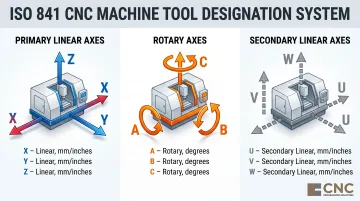
The axis designation system is defined by ISO 841, which establishes a framework encompassing up to nine standard axes (Sarkinen Calibrating, Mar 2026):
| Axis Type | Designations | Motion | Measurement Unit |
|---|---|---|---|
| Primary Linear | X, Y, Z | Straight-line translation | Inches or mm |
| Rotary | A, B, C | Rotation around X, Y, Z | Degrees |
| Secondary Linear | U, V, W | Parallel to X, Y, Z | Inches or mm |
- X, Y, Z — Primary linear axes; Z conventionally aligns with the machine spindle, setting the orientation for all other movements
- A, B, C — Rotary axes rotating around X, Y, and Z respectively, enabling angular tool approaches
- U, V, W — Secondary linear axes parallel to X, Y, and Z, adding degrees of freedom on machines with sub-spindles or secondary tool posts
Most shops use 4- or 5-axis configurations; 9-axis machines represent the full range and are typically found in Swiss-style screw machines and high-volume precision production.
How Rotary Axes Work in Practice
- A-axis — Allows the part or head to tip left and right (rotation around X)
- B-axis — Allows forward-and-backward tilting (rotation around Y)
- C-axis — Allows rotation around the vertical spindle (rotation around Z)
Together, these rotary axes let the tool approach the workpiece from virtually any angle without manual repositioning.
Indexed vs. Simultaneous Multi-Axis Machining
A critical operational distinction exists:
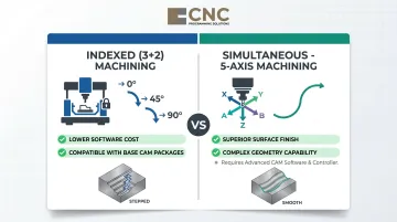
- Indexed (3+2 or positional) — The machine pauses, rotates to a set angle, and then cuts. The rotary axes position the workpiece but do not move during cutting
- Simultaneous (continuous) — All axes move at once to trace complex 3D contours in real time
Simultaneous 5-axis machining is more demanding on CAM programming but delivers superior surface finishes and geometric capability. Indexed capability is typically included in base CAD/CAM packages at little added cost. Simultaneous multi-axis, by contrast, requires more advanced software and controller capability.
Hardware Components Enabling Multi-Axis Operation
Three main systems enable multi-axis capability:
- Machine's physical capabilities — Torque, spindle speed, axis configuration, and structural rigidity
- CNC drive system — Servo motors, ball screws, positioning feedback sensors
- CNC controller — How input data is processed, stored, and executed
Rotary axis accuracy typically ranges from ±2 to ±20 arc-seconds with repeatability of ±2 to ±6 arc-seconds. Entry-level worm gear tables deliver approximately ±12.5 arc-seconds accuracy, while high-precision systems with encoders reach ±3 to ±5 arc-seconds (Sarkinen Calibrating, Mar 2026).
The Role of CAM Software
CAM (Computer-Aided Manufacturing) software translates 3D models into tool paths, generating the G-code the machine follows. It accounts for:
- Tool geometry and cutting parameters
- Stock dimensions and material properties
- Machine constraints and axis limits
- Collision avoidance — essential in multi-axis work where the tool, spindle, and fixtures can interfere
Siemens NX CAM, for example, integrates automated collision avoidance directly into multi-axis toolpaths and can reduce roughing time by up to 60% through adaptive milling strategies (Siemens NX CAM). In practice, CAM software is often where a machine's full multi-axis potential is either realized — or left on the table.
Types of Multi-Axis Machining Explained
3-Axis Machining
3-axis machining is the baseline: movement along X, Y, and Z only. Ideal for simpler parts—drilling holes, cutting flat surfaces, basic slots—where all features can be reached from a single direction.
Typical applications:
- Brackets and plates
- Housings and fixtures
- Simple molds and prototype parts
- Flat and contoured surfaces, pockets, slots, holes, 2.5D profiles
Parts requiring features on multiple faces must be repositioned manually, adding setup time and potential for error. The 3-axis segment held 30.2% of the multi-axis machining centers market in 2024, growing at 6.6% CAGR (Grand View Research).
4-Axis Machining
4-axis machining adds a rotary axis—typically the A-axis (rotation around X)—to the standard three linear axes. This is usually implemented via a rotary table or trunnion setup.
Key capabilities:
- Cylindrical parts with features around the circumference
- Helical features (spiral grooves, drilling tools)
- Cam lobes and angled holes
- Wrapped engravings and continuous rotary profiling
Indexed vs. continuous:
- Indexed 4-axis — Stop, rotate, cut
- Continuous 4-axis — Rotate while cutting
4-axis is the logical step up when features wrap around a cylinder or need to be accessed from the side. At CNC Programming Solutions, 4-axis milling is a core service — developed using advanced CAM software and tested programming strategies to hold tight tolerances on cylindrical and wrapped-feature components.
5-Axis Machining
5-axis adds a second rotary axis—B-axis (rotation around Y)—enabling the machine to approach five of the six faces of a part in a single setup. This is often implemented via a dual-axis trunnion or swiveling spindle head.
Why 5-axis is the gold standard:
- Dramatically reduces setup time (one setup vs. 4-6 setups)
- Maintains positional accuracy—no manual re-fixturing eliminates cumulative error
- Allows off-axis features and complex 3D contours with very tight tolerances
- Enables optimal tool-to-surface contact angles, improving surface finish and tool life
Real-world impact:
- A medical device part requiring 6 setups on a 3-axis machine was completed in a single setup on 5-axis, cutting delivery from 5 weeks to 2 weeks (Zenith Mfg, Sep 2025)
- An aerospace fuel nozzle redesigned as a monolithic 5-axis part achieved a 30% total cost reduction and eliminated a 15% scrap rate previously caused by welding and brazing failures
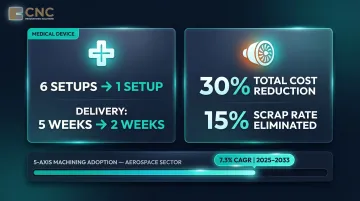
5-axis is the most widely adopted advanced configuration in aerospace, medical, and automotive industries. The aerospace end-use segment is projected to grow at 7.3% CAGR from 2025 to 2033 (Grand View Research).
Representative machines across price points include:
- Mazak VARIAXIS C-600 — Rigid C-frame construction with simultaneous 5-axis capability
- Haas UMC-500 — Entry-level 5-axis at US$156,995 (Haas Automation)
- DMG MORI DMC 85 MonoBlock — Used for space and defense work requiring tight tolerances in aluminum and nickel alloys
6-Axis and Beyond
6-Axis Machines add a third rotary degree of freedom (C-axis on a mill, A-axis on a lathe), enabling the spindle to orient the tool at any angle relative to any axis. This closes the capability gap between lathes and milling centers.
7-, 9-, and 12-Axis Configurations: These are full "machining centers" (not just mills or lathes) that can machine multiple parts or perform multiple operations simultaneously. Typical configurations include:
- 7-axis Swiss-style lathes — Citizen Cincom L12VII features 7 axes, 1/2-inch bar capacity, 15,000 RPM main spindle, and up to 28 mounted tools (Citizen Machines)
- 9-axis mill-turn centers — DN Solutions SMX2100 combines left and right spindles (C1, C2), B-axis milling head with 0.0001-degree precision, upper carriage (X1, Y, Z1), and lower turret (X2, Z2) (DN Solutions)
- Bumotec 191neo — 7-axis, 3-spindle multi-task production center for orthopedic implants, surgical instruments, and dental parts (Starrag/Bumotec)
These configurations make sense when cycle time, part complexity, and volume justify the investment — particularly in medical device production, watchmaking, and defense components where tolerances leave no room for multi-setup error accumulation.
Key Benefits of Multi-Axis Machining
Setup Consolidation: The Primary Value Driver
The most measurable benefit is the elimination of multiple setups. Each re-clamping introduces approximately ±0.0002 inches of positioning error; over 5 setups, cumulative error can reach ±0.001 inches or more.
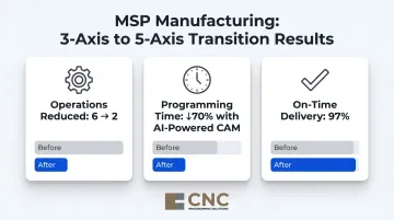
Case study: MSP Manufacturing (Bloomington, Indiana) transitioned from exclusively 3-axis milling to 5-axis capability using Haas UMC 750 and UMC 500 SS machines. Results:
- Production schedules condensed from 6 operations to 2
- Programming time dropped by approximately 70% using AI-powered CAM
- Achieved a 97% on-time delivery rate after implementing 5-axis workflows (Modern Machine Shop, Jun 2025)
Precision and Surface Finish Advantages
With more axes, the tool can move tangentially across the part surface rather than indexing in steps. This produces:
- Smoother finishes
- Better geometric accuracy
- Longer tool life due to optimal tool-to-surface contact angles
Meyer Tool (profiled in Modern Machine Shop) reported that simultaneous 5-axis produces finishes that "look like a mirror" — a result of eliminating the dwell marks that step-indexing leaves behind.
Reduced Error and Higher Repeatability
Multi-axis machining removes most manual intervention from the process. What once required 4–5 setups can be completed in a single clamping, cutting cumulative positional error and delivering more consistent output across production runs.
Parts with positional tolerances tighter than ±0.002 inches (±0.05 mm) are recommended for 5-axis single-setup machining to avoid error stack-up (Zenith Mfg, Sep 2025). That consistency also translates directly into capacity — fewer rejected parts mean more machine time spent on productive cuts.
Machine Uptime and Monitoring ROI
Coastal Machine and Supply increased utilization of its DMG MORI DMC 85 five-axis machine by 46% over the first two months of 2026 after implementing machine monitoring software that sends alerts if a machine is idle for more than 15 minutes (Modern Machine Shop, Apr 2026).
Industries That Use Multi-Axis Machining
Aerospace and Defense
Modern Machine Shop describes aerospace machining as "often associated with tight tolerances, hard-to-machine metals and complex contours" where "large-travel five-axis machine tools are routine" (MMS Aerospace Topic Page).
Why multi-axis is critical:
- Complex airfoil geometries and turbine blades
- Structural components with tight tolerances (typically 0.002 to 0.003 inches)
- Materials like titanium and high-nickel alloys
Coastal Machine and Supply derives approximately 60% of revenue from space and defense contracts (MMS, Apr 2025). The aerospace end-use segment is projected to grow at 7.3% CAGR from 2025 to 2033.
Medical Devices
Multi-axis machining is essential for medical components because implant geometries—hip cups, spinal cages, knee femoral components—feature complex freeform surfaces that cannot be reached from a single orientation.
Typical applications:
- Custom implants (hip replacements, spinal cages)
- Dental prosthetics
- Surgical instruments machined from titanium and cobalt-chrome
Biocompatible materials are expensive enough that minimizing scrap through single-setup machining offers significant material cost savings. The Bumotec 191neo handles orthopedic implants and surgical instruments, cutting titanium, stainless steel, and precious metals (Starrag/Bumotec).
Automotive
The automotive sector represents the largest end-use segment at 39.7% of the multi-axis machining centers market in 2024 (Grand View Research).
Applications:
- Engine cylinder machining
- Transmission components
- Complex mold and die work for body panels and interior components
High-volume production environments justify 5-axis capital costs through fewer setups, less part handling, and faster throughput — all of which matter when running thousands of identical components.
Energy and Oil/Gas
Multi-axis capability serves energy-sector components such as:
- Turbine parts
- Valve bodies and pressure-containing parts
- Pump housings and subsea manifold components
Coastal Machine and Supply's business mix—40% oil and gas alongside 60% defense—demonstrates how 5-axis investment enables diversification across sectors (MMS, Apr 2025).
Multi-axis machining also supports rapid prototyping, where producing accurate metal or plastic models quickly — without multiple setups — compresses development timelines significantly.
Choosing the Right Multi-Axis Setup for Your Needs
Practical Decision Framework
When to use 3-axis:
- Part only requires machining on one or two flat faces
- No off-axis features
- Cost-effectiveness is paramount
When to use 4-axis:
- Features wrap around a cylinder
- Need to access features from the side
- Cylindrical parts with radial features
When to use 5-axis:
- Part has complex 3D contours
- Tight tolerances on multiple faces
- Cannot be repositioned without losing accuracy
- Positional tolerances tighter than ±0.002 inches
Capital Cost Benchmarks
Haas Automation provides transparent USD pricing:
| Model | Axis Count | Published Price (USD) |
|---|---|---|
| Haas VF-1 | 3-axis | $66,995 |
| Haas VF-2 | 3-axis | $70,995 |
| Haas UMC-500 | 5-axis | $156,995 |
The 5-axis UMC-500 costs approximately 2.2x the price of a comparable 3-axis VF-2. Note that Haas represents the value end of the 5-axis market; higher-end European or Japanese machines can reach $300,000–$500,000 or more.
Cost and Complexity Trade-Offs
Multi-axis machines—especially 5-axis—are significantly more expensive to purchase and operate than 3-axis centers, and they require more sophisticated CAM programming and skilled operators.
Hourly rate comparison:
- 3-axis work: $75 to $125 per hour
- 5-axis work: $150 to $325 per hour — a 2x to 3x differential
That rate gap narrows in practice: setup consolidation eliminates rework and reduces scrap, often bringing total part cost down despite the higher hourly figure.
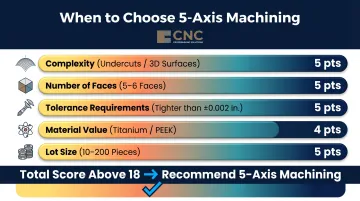
Decision scoring framework: Zenith Mfg recommends 5-axis machining when a project scores above 18 points across five factors:
- Complexity (undercuts/3D surfaces = 5 pts)
- Number of faces requiring machining (5-6 faces = 5 pts)
- Tolerance requirements (tighter than ±0.002 in. = 5 pts)
- Material value (titanium/PEEK = 4 pts)
- Lot size (10-200 pieces = 5 pts)
Outsourcing as an Alternative
The ROI case for multi-axis is strongest when part complexity, production volume, and tolerance requirements justify the investment. Outsourcing to a capable multi-axis CNC programming and machining partner can be a cost-effective alternative to in-house investment.
CNC Programming Solutions, for example, develops CNC programs for machines up to 5 axes — handling the programming complexity without requiring clients to invest in additional equipment or in-house expertise.
Key Selection Factors
Whether you're buying a machine or sourcing a partner, the same criteria drive the decision. Evaluate:
- Part geometry complexity
- Number of faces requiring machining
- Tolerance requirements
- Material type
- Batch size
- Available budget
Frequently Asked Questions
What is multi-axis machining?
Multi-axis machining is a CNC manufacturing process in which the cutting tool or workpiece moves in four or more directions (axes), allowing complex parts to be made in fewer setups with greater precision than traditional 3-axis machining.
What is the difference between 3-axis, 4-axis, and 5-axis machining?
3-axis moves along X, Y, and Z only; 4-axis adds one rotary axis (A) for cylindrical and circumferential features; 5-axis adds a second rotary axis (B), enabling access to five faces of a part in a single setup for the most complex geometries and tightest tolerances.
Is 5-axis CNC worth the investment?
5-axis machining pays off for complex, high-tolerance parts — it cuts setup time, reduces error accumulation, and produces better surface finishes in one pass. For simpler geometries, 3- or 4-axis machining is typically more cost-effective.
Which CNC machine is best suited for high-precision aerospace components?
5-axis CNC machining centers are the standard choice for aerospace components due to their ability to machine complex geometries, curved surfaces, and multi-face features in a single setup—meeting the tight tolerances and surface finish requirements aerospace certification demands.
Do 6-axis or 7-axis CNC machines exist, and what is a 4th-axis machine?
Yes, 6-, 7-, 9-, and even 12-axis machining centers exist—used in high-volume precision production and Swiss-style screw machining. A 4th-axis machine is a 3-axis CNC mill or lathe fitted with an additional rotary axis (A-axis), allowing parts to be indexed or continuously rotated during cutting.
How do you ensure quality and precision in your machining work?
Precision in multi-axis machining depends on several interconnected factors:
- Machine calibration to maintain dimensional accuracy
- CAM toolpath strategies that account for collision avoidance and optimal tool angles
- Skilled operators who understand material behavior and setup requirements
- In-process inspection and surface finish verification throughout production