Introduction
In medical device development, a single design flaw that reaches production can compromise patient safety and trigger costly recalls. According to FDA recall data, manufacturing-related issues account for over 30% of medical device recalls annually. CNC machining prototypes exist to prevent this scenario by catching design failures before they reach clinical use.
Medical device CNC machining prototypes are high-precision physical parts produced via computer-controlled cutting of solid material. These prototypes test fit, form, and function before committing to full production, giving engineers a tangible part to validate before clinical use begins.
This guide covers:
- Why CNC machining leads in medical prototyping
- The step-by-step development process
- Material selection criteria and surface finishing requirements
- Regulatory compliance factors
- How CNC compares to other prototyping methods
Key Takeaways
- CNC machining achieves tolerances of ±0.001" or tighter, enabling functional and regulatory-grade medical device testing
- Prototypes move through CAD design, iterative refinement, verification testing, and pilot production in sequence
- Material selection—titanium, PEEK, stainless steel, or medical-grade polymers—depends on device type and development stage
- Surface finishing affects sterilizability, biocompatibility, and regulatory acceptance—not just aesthetics
- CNC outperforms 3D printing for functional validation-grade prototypes and bridges directly into low-volume production
Why CNC Machining Is the Gold Standard for Medical Device Prototypes
Precision That Meets Clinical Requirements
CNC machining delivers the dimensional accuracy medical devices demand. Precision CNC turning achieves tolerances of ±0.001" routinely, with high-end work reaching ±0.0003" for critical implant components such as heart valve parts. Medical machining achieves positional resolution down to 0.1 microns using linear glass scales for surgical instruments and implant features where even minor deviations affect clinical performance.
Bone screws with interference fit require tolerances as tight as +0/-5 microns, and catheter tips control fluid flow through bore diameters below 200 microns—dimensions achievable only through precision CNC processes.
Repeatability Across Production Scaling
That precision only matters if it holds across every unit. CNC turning for implantable devices achieves 99.98% repeatability in production, meaning the same program that creates a single prototype scales to thousands of identical parts without process changes.
This repeatability is non-negotiable when transitioning from prototype to clinical-trial batch or pilot production. Production-grade CNC systems maintain this consistency through:
- Machine mapping to track positional drift over time
- Volumetric accuracy checks using laser calibration before each run
- Automatic tool wear compensation after every in-process measurement
Complex Geometry in Single Setups
Repeatability alone doesn't cover the complexity of modern medical components. Modern multi-axis CNC systems—4-axis and 5-axis—machine intricate contours, undercuts, and internal features in a single setup. Five-axis simultaneous machining enables organic curves and compound angles impossible on 3-axis machines. Sub-spindle integration allows multi-side machining while preserving alignment across all surfaces.
It's what makes components like these manufacturable:
- Bone-anchoring screws with complex thread geometries
- Catheter fittings with internal fluid pathways
- Endoscopic tool housings with compound angles
- Spinal fixation rods with anatomical contours
Material Versatility Without Restrictions
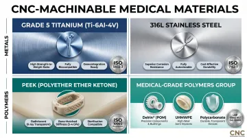
Geometry capability pairs with equally broad material flexibility. CNC machining handles the full spectrum of medical-grade metals and engineered plastics without the material restrictions found in additive or casting processes. The method works with:
- Grade 5 titanium (Ti-6Al-4V) for implantable devices
- 316L stainless steel for surgical instruments
- PEEK for radiolucent spinal applications
- Medical-grade polymers including Delrin, polycarbonate, and UHMWPE
Each material type is machined from the same stock materials used in final production, ensuring prototype test results transfer directly to production devices. Dedicated medical cells prevent cross-contamination, and cutting fluids meet USP Class VI biocompatibility standards.
Rapid Design Iteration Cycles
CNC machining runs directly from digital CAD files, so design changes require only a reprogrammed toolpath—no new molds or tooling. This makes rapid iteration practical and cost-effective throughout prototype development. When a fit issue emerges during functional testing, engineers can modify the CAD model, regenerate the toolpath, and have a revised prototype in days rather than the weeks a new mold or casting would require.
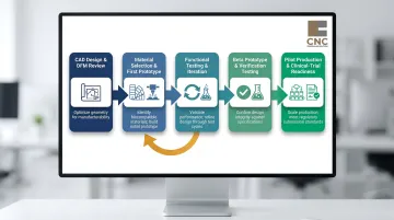
The CNC Medical Device Prototype Development Process
Stage 1: CAD Design and DFM Review
The process begins with a detailed 3D CAD model and a design-for-manufacturability review. This review confirms the geometry is achievable within medical tolerance requirements and flags features that may add unnecessary cost or lead time. Engineers assess whether undercuts require special tooling, whether wall thicknesses support machining without deflection, and whether tolerance specifications are realistic for the chosen material.
DFM review catches issues such as:
- Thin-wall sections that vibrate during machining
- Internal features inaccessible to cutting tools
- Tolerance stack-ups that create assembly problems
Stage 2: Material Selection and First Prototype
Engineers select an appropriate material for the prototype stage, often matching or approximating the final production material. For implantable device prototypes, this typically means Grade 5 titanium or 316L stainless steel from the start. For housings and enclosures, medical-grade polycarbonate or PEEK may serve as surrogates during early iterations before transitioning to production-grade materials.
The CNC machine shop programs toolpaths, selects appropriate cutting tools, and produces the first physical prototype for dimensional inspection. First-article inspection confirms critical dimensions match design intent before functional testing begins.
Stage 3: Functional Testing and Iteration
The prototype undergoes evaluation for fit, mechanical function, ergonomics, and preliminary safety. An orthopedic implant prototype might reveal interference issues during assembly; a surgical instrument prototype might expose ergonomic problems during simulated use. Failures identified here trigger design revisions and re-machining — and this iteration cycle may repeat several times.
The cost math is straightforward: catching flaws at this stage runs hundreds or thousands of dollars. Research shows that early-stage design changes are exponentially cheaper than corrections during clinical trials or after production launch, where the same fix can cost millions.
Stage 4: Beta Prototype and Verification Testing
The beta prototype represents a near-production-representative part used for rigorous verification testing: mechanical stress testing, sterilization resistance, and biocompatibility screening. At this stage, materials, finishes, and tolerances should match final production specifications exactly.
Design verification confirms that design output meets design input — confirming the device was designed correctly. CNC-machined beta prototypes using production-equivalent materials are the standard vehicle for generating verification test data, faithfully replicating the mechanical, thermal, and biocompatibility properties of the final device.
Stage 5: Pilot Production and Clinical-Trial Readiness
The transition from single prototype to controlled small batch marks a critical milestone. Process consistency and documentation become core requirements for FDA submission readiness. The Design History File (DHF) and Device Master Record (DMR) require traceable records of material certifications, inspection reports, and revision-controlled CAD files.
Pre-production prototypes essentially mirror the final product and often serve as devices used in clinical trials and regulatory submissions. At this stage, manufacturing processes must be validated and repeatable.
Materials Used in CNC Machined Medical Device Prototypes
Metals
Titanium (Grade 5 / Ti-6Al-4V)
Ti-6Al-4V is the gold standard for replacing missing teeth and orthopedic implants, governed by ISO 5832-3 and ASTM F136. The material offers high strength-to-weight ratio, corrosion resistance, and proven biocompatibility under ISO 10993 testing. The ELI (Extra-Low Interstitials) variant provides improved ductility and fracture toughness.
Applications include:
- Femoral stems and acetabular cups
- Dental implants and abutments
- Trauma fixation plates and screws
- Spinal fusion cages
316L Stainless Steel
316L's low carbon content and molybdenum addition deliver superior corrosion and oxidation resistance — critical for instruments exposed to repeated steam autoclave cycles. Governed by ISO 7153-1 and ASTM F899, it withstands harsh sterilization when paired with proper passivation per ASTM A967.
For applications where sterilization ease, toughness, and cost efficiency outweigh the biocompatibility advantages of titanium, 316L is the standard choice. Typical applications include:
- Surgical instrument bodies and handles
- Reusable device housings
- Non-implant medical hardware and enclosures
- Prototyping fixtures and surgical guides
Engineered Plastics and Polymers
When weight reduction, radiolucency, or bone-matched stiffness is the design priority, engineered polymers take over from metals. PEEK leads this category for implant-grade applications, with medical-grade commodity plastics filling out the non-implant and concept prototype tier.
PEEK (Polyether Ether Ketone)
PEEK is covered by ASTM F2026 and recognized by the FDA as a consensus standard for surgical implant applications. The polymer provides radiolucency for imaging compatibility, chemical resistance to sterilization agents, and a modulus of elasticity closer to bone than metal implants.
CNC machining of PEEK achieves surface finishes as fine as Ra < 0.02 µm for articulating surfaces and implant-bone interfaces. Orthopedic machining tolerances for PEEK spinal and trauma systems frequently approach ±0.01 mm or better. Applications include spinal implant prototypes, instrument handles, and radiolucent fixation devices.
Medical-Grade Polymers
| Material | Standard | Key Properties | Typical Applications |
|---|---|---|---|
| Delrin (Acetal) | ASTM F1855-00 | Dimensional stability, chemical resistance, biocompatibility | Instrument handles, drug delivery components, enclosures |
| UHMWPE | ASTM F648 | Wear resistance, high impact resistance, biocompatible | Orthopedic bearing surfaces (hip, knee), spinal devices |
| Polycarbonate | USP Class VI eligible | Optical clarity, impact resistance, sterilizable | Diagnostic housings, enclosures, fluid pathways |
The FDA recommends including a declaration of conformity to ASTM F648 in premarket submissions for devices incorporating UHMWPE. For early-stage concept validation, Delrin and polycarbonate are the practical starting point — lower material cost and easier machining let teams iterate quickly before committing to PEEK or metal for final prototypes.
Surface Finishing and Post-Processing for Medical Prototypes
Surface Roughness Directly Impacts Performance
Surface finish directly determines medical device performance and regulatory acceptance. Surfaces rougher than Ra 0.8 µm harbor bacteria and compromise sterilization efficacy, while ultra-smooth articulating surfaces minimize wear debris generation over decades of implant use.
Ra (Roughness Average) Requirements by Application:
| Application | Target Ra Range | Rationale |
|---|---|---|
| Articulating implant surfaces (femoral head) | Ra 0.015-0.05 µm | Minimize wear debris generation |
| Surgical instruments | < Ra 0.8 µm | Prevent biofilm formation; ensure sterilization efficacy |
| Osseointegration surfaces | Ra 1-5 µm (intentionally rough) | Promote bone in-growth at implant-bone interface |
| Standard CNC machined parts | Ra 0.8-3.2 µm | Baseline as-machined finish |
Key Finishing Processes
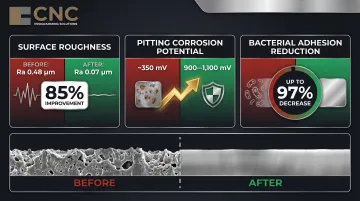
Electropolishing
Electropolishing of 316L stainless steel reduces average surface roughness from 0.48 µm to 0.07 µm — an 85% improvement. The process creates a denser chromium oxide passive layer (3-5 nm vs. 1-2 nm standard), yielding measurable gains across three performance areas:
- Corrosion resistance: Pitting potential rises from ~350 mV to 900-1,100 mV
- Bacterial adhesion: Decreases by up to 97% through removal of microscopic crevices
- Passive layer density: 3-5 nm oxide layer vs. 1-2 nm from standard machining
Bead Blasting
Bead blasting creates controlled surface textures that improve coating adhesion and remove surface stress risers left by machining. In medical device applications, it is commonly used on housings, enclosures, and instrument handles where a uniform matte finish aids grip and downstream coating processes.
Anodizing
Type II (sulfuric acid) and Type III (hardcoat) anodizing per MIL-A-8625 are used on aluminum medical device housings and enclosures. Type III hardcoat anodizing produces a dense aluminum oxide layer that increases surface hardness and wear resistance. Both types apply to non-implant components — hardcoat is preferred where abrasion resistance is a primary concern.
Finishing Choices Impact Regulatory Testing
Finishing choices at the prototype stage should anticipate production finishing requirements. Surface-dependent test results—biocompatibility screening, sterilization validation—must carry forward to the final device. If a beta prototype undergoes biocompatibility testing with an electropolished surface, the production device must also be electropolished to the same specification.
This regulatory continuity is where finishing partner selection matters. CNC Programming Solutions provides bead blasting, vibe deburring, anodizing, and powder coating services aligned to prototype-stage requirements, so the surface specifications established during testing can be replicated consistently into production.
Regulatory Compliance and Quality Standards in CNC Medical Prototyping
FDA QMSR: The New 21 CFR Part 820
Effective February 2, 2026, the FDA's Quality Management System Regulation (QMSR) incorporates ISO 13485:2016 by reference. Under QMSR, ISO 13485 compliance is a legal requirement for medical device manufacturers and their CNC machining suppliers.
Key changes affecting CNC machining documentation:
- The Design History File (DHF) now aligns with ISO 13485 "Design and Development File" (Clause 7.3.10)
- The Device Master Record (DMR) now aligns with ISO 13485 "Medical Device File" (Clause 4.2.3)
- FDA has authority to inspect management review, quality audits, and supplier audit reports
CNC machining documentation—material certifications, inspection reports, revision-controlled CAD files—forms the backbone of a compliant Design History File. Traceability from prototype through production is now a regulatory requirement, not just a quality best practice.
ISO 13485 Quality Management Requirements
ISO 13485:2016 alignment is now mandatory for CNC machining suppliers serving medical device manufacturers. This includes documented quality management systems, process validation, traceability of materials and operations, and controlled environments.
When vetting a machining shop for medical device work, confirm:
- ISO 13485 certification or documented alignment with its requirements
- Material traceability systems that link raw material certifications to finished parts
- Calibrated inspection equipment with documented calibration schedules
- Environmental controls for cleanliness and contamination prevention
- Documented change control procedures for design revisions
Material compliance is the next layer of this framework. ISO 13485 governs your machining supplier's processes; ISO 10993 governs the materials those processes touch.
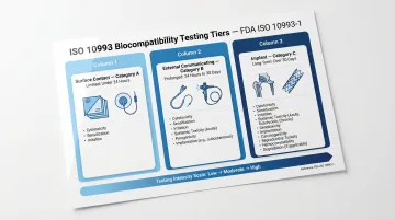
ISO 10993 Biocompatibility Testing: Phased Approach
The FDA's September 2023 guidance on ISO 10993-1 establishes a risk-based approach to biocompatibility evaluation. The guidance supports phased testing: at early feasibility stages, "it may be acceptable to provide complete biocompatibility information once the device design is finalized for commercialization, depending on the risks posed to patients."
This means:
- Prototype materials and finishes should be selected early in the CNC process
- Early-stage prototypes may undergo partial biocompatibility testing
- Complete evaluation is required once design is finalized for commercialization
- Switching materials after partial testing restarts the biocompatibility evaluation clock — adding weeks and cost to the development timeline.
Testing scope scales with how the device contacts the body:
| Contact Type | Duration Category | Examples |
|---|---|---|
| Surface contact | A: Limited (<24 h) | Surgical drapes, electrodes |
| External communicating | B: Prolonged (>24 h–30 d) | Catheters, endoscopes |
| Implant | C: Long term (>30 d) | Orthopedic implants, stents |
CNC Machining vs. Other Prototyping Methods for Medical Devices
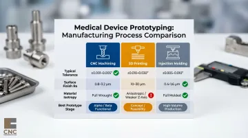
Dimensional Accuracy: CNC's 3-10x Precision Advantage
CNC machining achieves ±0.001-0.005" tolerances compared to 3D printing's ±0.010-0.030"—a 3-10x precision advantage that matters critically for functional medical prototypes. Standard CNC work produces Ra 0.8-3.2 µm surface finishes, while additive manufacturing yields Ra 10-30 µm requiring extensive post-processing to reach medical-grade smoothness.
Key Comparison:
| Method | Typical Tolerance | Surface Finish (Ra) | Material Isotropy |
|---|---|---|---|
| CNC Machining | ±0.001-0.005" | 0.8-3.2 µm | Full (wrought stock) |
| 3D Printing | ±0.010-0.030" | 10-30 µm | Anisotropic (weaker in Z) |
| Injection Molding | ±0.005-0.010" | 0.4-1.6 µm | Full (molded) |
These numbers have practical consequences. 3D printing's anisotropy—parts that are measurably weaker along the Z-axis—limits structural reliability in load-bearing applications. For medical prototypes where material property fidelity drives regulatory acceptance, CNC machining's full isotropy from wrought stock makes it the clear choice for functional verification work.
Injection Molding Transition Economics
That precision advantage comes with a cost structure worth understanding before committing to tooling. Injection molding requires $2,000-$5,000 for aluminum molds or $5,000-$100,000+ for steel, and the break-even point typically lands between 1,000 and 5,000 units—below that threshold, CNC machining is more cost-effective.
CNC costs are relatively linear because there is no expensive mold; your 1st part and your 100th part cost roughly the same, minus setup amortization. This predictability makes CNC the natural bridge between early-stage 3D-printed concepts and high-volume injection-molded production.
The Hybrid Development Framework
Each prototyping method has a defined role across the development lifecycle:
- Concept/Proof-of-Concept — 3D printing for rapid iteration at lowest cost; answers fundamental feasibility questions fast.
- Alpha/Functional Prototyping — CNC machining enters when material properties and precise tolerances matter; parts begin to behave like actual devices.
- Beta/Design Verification — CNC is the primary method, delivering functional prototypes with production-equivalent materials for rigorous testing.
- Pilot/Production Validation — Injection molding or production CNC validates manufacturing processes at scale ahead of full commercialization.
Choosing the right method at the wrong stage wastes time and budget. Matching the process to the question being answered is what keeps medical device programs on schedule.
Frequently Asked Questions
What tolerances can CNC machining achieve for medical device prototypes?
Precision CNC machining routinely achieves tolerances of ±0.001" or tighter, with high-end shops reaching ±0.0003" for critical features such as heart valve components and bone screw threads. These tolerances meet the dimensional requirements for most surgical instruments and implant components.
What materials are most commonly used in CNC machined medical device prototypes?
The most common choices are Grade 5 titanium (Ti-6Al-4V) and 316L stainless steel for metal components, and PEEK or medical-grade polycarbonate for polymer parts. Selection depends on whether the device is implantable or instrument-based, the prototype stage, and performance requirements such as radiolucency or wear resistance.
How does CNC machining compare to 3D printing for medical device prototyping?
CNC machining delivers superior dimensional accuracy (±0.001" vs. ±0.010"), material integrity from wrought stock, and surface finish (Ra 0.8–3.2 µm vs. Ra 10–30 µm) for functional validation prototypes. 3D printing is better suited for rapid early-concept geometry checks where material fidelity is less critical.
What FDA requirements apply to CNC machined medical device prototypes?
Prototypes used in design verification must comply with 21 CFR Part 820 Design Controls (effective February 2, 2026), which incorporates ISO 13485:2016 by reference. Required documentation — material certifications, dimensional inspection records, and revision-controlled CAD drawings — forms the Design History File (DHF) for regulatory submission.
How long does it take to produce a CNC machined medical device prototype?
Lead times generally run 1–5 business days for simple single-part prototypes to 2–4 weeks for complex multi-component assemblies requiring tight tolerances and specialized finishing. Design-for-manufacturability review upfront reduces iteration cycles and overall development time.
Can CNC machined prototypes be used directly in clinical trials?
Beta-stage CNC prototypes made from production-equivalent materials can support clinical evaluations if they meet ISO and FDA documentation requirements and have passed functional and biocompatibility testing. Under the FDA's phased approach to ISO 10993, certain biocompatibility evaluations may run in parallel with early-stage clinical data collection.