Introduction
Impellers rank among the most geometrically demanding components in modern manufacturing. Twisted blades, tight inter-blade channels, and simultaneous hub and shroud constraints create a machining environment where deviation isn't just cosmetic—it's catastrophic. A blade surface discontinuity of just a few microns can trigger flow disturbances, slash efficiency, and accelerate vibration-induced failure.
The performance stakes are measurable. According to research published in Physics of Fluids, under full cavitation conditions, impeller entropy production accounts for up to 50% of total pump energy loss—meaning machining accuracy directly controls hydraulic performance.
Getting that accuracy right requires the right motion strategy, tooling, and CAM setup from the start. This guide covers why 5-axis simultaneous motion is the industry standard, how the process works step by step, what tooling and CAM strategies produce reliable results, and which failure modes to anticipate. Whether you're programming your first closed impeller or refining an existing process, the strategies here will help you maintain geometric consistency, reduce scrap, and deliver parts that meet spec.
TLDR:
- 5-axis simultaneous motion is required for blade surface accuracy and setup consolidation
- Closed impellers can exceed 30% scrap rates without proper CAM strategy and collision avoidance
- Use 60–100 SFM on Inconel 718; expect tool life of 20–40 minutes per edge
- Flow channel surfaces require Ra 0.8-1.6 μm finish to prevent efficiency losses
- Balancing grade G2.5 is the target for high-performance applications; geometric consistency reduces correction mass
What Is an Impeller and Why Blade Geometry Is the Real Challenge
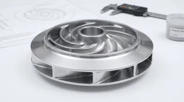
An impeller is a rotating component that transfers mechanical energy into fluid motion through curved blade surfaces. Its function depends entirely on precise blade form, hub concentricity, and surface continuity—not just approximate shape. The U.S. DOE Engineering Handbook defines impellers by construction: open types consist of blades attached to a hub; semi-open designs add a circular plate on one side; enclosed (shrouded) types have plates on both sides. In all cases, the blades impart radial and rotary motion to the liquid, forcing it to the outer periphery.
Key Structural Components from a Machining Standpoint
- Hub and bore — Carries mechanical load and governs concentricity; any runout here propagates directly into dynamic imbalance
- Blades — Aerodynamic surfaces that must be smooth, consistent, and held within tight profile tolerances
- Shroud — Encloses the flow channel in closed designs, severely restricting tool access
- Rear face — Used for balance correction mass removal after final machining
Why Blade Geometry Controls Performance
Small deviations in blade angles, thickness, and surface finish affect flow efficiency and hydraulic losses. Amarinth's analysis of API 610 test tolerances confirms that variations in impeller clearances and blade form impact leakage losses and pump head.
Surface roughness compounds these losses. Blade roughness disrupts the stable flow path within the channel, causes vacuole collapse, and enlarges vortex structures. During full cavitation, impeller entropy production can account for 50% of total energy loss.
That's why impeller machining is a geometry control problem above all else. Every decision—from toolpath strategy to finishing passes—has a measurable effect on performance. Even toolpath transitions that leave witness marks create flow disturbances that reduce efficiency and increase noise.
Why Impellers Require 5-Axis CNC Machining
Impeller blade surfaces are fully three-dimensional and continuously curved in all directions simultaneously. 3-axis motion cannot maintain correct tool orientation across these surfaces without multiple repositioning setups, each introducing cumulative alignment error and surface discontinuity.
Industry sources confirm that impellers almost always require 5-axis CNC machining—not as a preference, but as a functional necessity. The hydraulic performance of an impeller depends on blade geometry, hub alignment, and flow surface consistency, none of which hold reliably with 3-axis motion.
How 5-Axis Motion Solves the Problem
5-axis machining keeps the cutting tool continuously normal (or at a controlled lead/lag angle) to the blade surface throughout the entire cut. This enables:
- Smooth, continuous toolpath transitions across blade surfaces
- Consistent chip load across varying surface angles
- Uniform surface finish on the entire blade profile
- Completion of complex geometry in a single coordinated operation
DMG Mori's published impeller machining example demonstrates simultaneous 5-axis high-speed milling on an A5052 aluminum impeller (diameter 600 mm × 200 mm) with a cycle time of 322 minutes using an 18,000 rpm spindle. The entire blade system is machined in one setup, preserving concentricity between bore and blade surfaces.
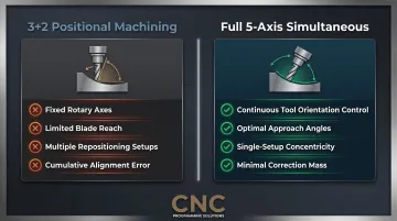
The Limitation of 3+2 Positional Machining
3+2 (positional) machining locks the rotary axes at a fixed angle while the machine cuts using three linear axes. While this offers rigidity, it cannot reach all blade geometry without awkward approach angles, long tool overhang, and significant air cuts—particularly in deep, narrow inter-blade channels where vibration and deflection compound.
Full simultaneous 5-axis motion avoids these constraints entirely. The tool approaches from optimal angles throughout the cut, reducing required tool length, improving rigidity, and enabling stable cutting conditions inside closed impeller flow channels where access is severely restricted.
Setup Consolidation Preserves Concentricity
Consolidating the entire impeller into one or two 5-axis setups preserves concentricity between the bore and blade system—critical for dynamic balancing. A geometrically stable part produced in one setup requires far less correction than one built across multiple repositioned operations.
ISO 21940-11 specifies balance grade G2.5 for turbine-driven pumps and turbo compressors. Excessive correction mass during balancing typically points back to geometric instability introduced during machining.
Types of Impellers and Their Machining Challenges
Open Impellers
Open impellers consist of blades attached to a hub with no front shroud. This is the most accessible design for machining—blade surfaces are fully exposed, allowing straightforward roughing and finishing with 5-axis control. However, the absence of a shroud means blade tip thickness and edge consistency must be tightly controlled to prevent deformation during cutting. Thin blade tips are vulnerable to deflection from cutting forces, and any deviation in tip geometry directly affects clearance and efficiency.
Semi-Open and Closed Impellers
Semi-open impellers add a partial shroud, which improves structural stiffness but restricts tool access along blade tips. Careful tool orientation management is required to maintain clearance and surface quality in confined areas.
Closed impellers (full front and rear shrouds) present the most demanding machining challenge. Severely limited tool access inside the flow channel forces long-reach tooling. Any geometric error in internal blade surfaces translates directly into hydraulic performance losses — a compounding problem in high-duty-cycle applications.
The machining risk is measurable. According to LS Manufacturing's analysis, closed impellers in challenging alloys can exceed 30% scrap rates due to chatter and distortion without deterministic manufacturing approaches. Key contributors include:
- Long-reach tooling deflection under cutting loads
- Chatter buildup in confined flow channels
- Distortion from residual stress in thin-walled alloys
- Geometric error accumulation across multiple setups
Testing published in Pumps and Systems showed that adding a shroud to an open impeller increased flow from 360 gpm to 400 gpm and boosted efficiency by up to 5.3%. For most duty-cycle applications, that performance premium justifies the added machining cost.
Step-by-Step 5-Axis Impeller Machining Process
Design Review and CAM Strategy
The process begins with detailed review of blade geometry, tolerance zones, and functional surface requirements before any toolpaths are created. CAM strategy decisions made at this stage—continuous surface motion, axis tilt control, cutter engagement management—determine whether the finished part meets spec or requires costly rework.
Key decisions include:
- Flank milling vs. point milling strategy based on blade ruled surface geometry
- Collision avoidance approach for inter-blade channels
- Stock allowance for semi-finishing to prevent thin-wall distortion
- Axis priority and machine kinematics optimization
Rough Machining
Roughing focuses on efficient bulk material removal while protecting the blank's structural integrity. 5-axis plunge roughing is a preferred strategy because cutting forces are aligned with the tool's center axis, minimizing deflection and extending tool life—especially important in deep inter-blade channels where long tools are unavoidable.
Open Mind's hyperMILL Multiblade package includes a dedicated plunge roughing module designed specifically for pockets between blades, used when horizontal feed rates are ineffective due to long, slim tools. Concepts NREC's MAX-PAC uses "box passes" for roughing integrally shrouded geometries combined with 3+2 roughing that balances multi-axis flexibility with 3-axis rigidity.
Semi-Finishing
Semi-finishing establishes near-net blade form and prepares surfaces for finishing. Stock left at this stage must be controlled carefully and uniformly—too little risks overcutting critical surfaces during finishing, too much creates uneven engagement and vibration on thin blades.
According to research on thin-walled titanium impellers, excessive stock allowance may cause deformation during finishing on blade components as thin as 0.6 mm. Optimized variable feed machining strategies result in a 20% reduction in titanium impeller processing time, with variable feed rates based on part stability reducing total cycle time by as much as 25%.
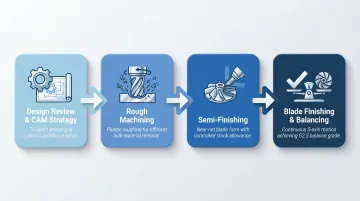
Blade Finishing
Blade finishing defines final aerodynamic surfaces. Continuous 5-axis motion must be maintained throughout to avoid toolpath discontinuities that leave witness marks. The tool axis must be controlled to maintain a consistent lag or lead angle that produces optimal surface contact and avoids chatter on thin blade sections.
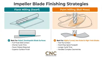
Two primary finishing strategies apply depending on blade geometry:
- Flank milling (swarf cutting): Uses full flute engagement along the blade height; preferred for ruled blade surfaces because it produces superior finish in fewer passes
- Multi-pass ball-nose finishing: Required for warped or complex blade profiles where controlled axis tilt prevents collisions and maintains surface integrity
Hub, Bore, and Balance Operations
Once blade geometry is stabilized, hub bore and drive interface features are finished to maintain concentricity. Dynamic balancing follows as the final step.
ISO 21940-11 defines balance grades for rotating machinery:
| Balance Grade | Vibration Velocity | Applicable Rotor Types |
|---|---|---|
| G6.3 | 6.3 mm/s | Standard pump impellers, fans, general machinery |
| G2.5 | 2.5 mm/s | Turbine-driven pumps, turbo compressors, gas/steam turbines |
| G1.0 | 1.0 mm/s | Automotive turbochargers, high-speed turbomachinery |
| G0.4 | 0.4 mm/s | Gyroscopes, spindles, high-precision drives |
A geometrically consistent impeller produced through proper 5-axis sequencing requires minimal correction mass. Excessive correction indicates upstream geometric instability—typically from blade-to-blade variation or hub/bore misalignment.
CAM Programming Strategies and Tooling Best Practices
Flank Milling vs. Point Milling
Flank milling (swarf cutting) uses side-of-tool contact against the blade wall. It's preferred for ruled blade surfaces because it produces a superior finish in fewer passes. Concepts NREC's MAX-PAC flank milling module automatically minimizes surface deviations and balances machine motion against accuracy requirements.
Point milling (ball-nose finishing) uses tool tip contact with continuous spiral movements. This approach is required for highly curved, non-ruled blades — MAX-PAC's point milling module is specifically recommended for blisks and high-twist geometries where flank milling isn't viable.
| Strategy | Best For | Mechanism | Cycle Time |
|---|---|---|---|
| Flank milling (swarf) | Ruled blade surfaces | Full flute engagement along blade height | Shorter - fewer passes |
| Point milling (ball-nose) | Highly curved, non-ruled blades | Tool tip/point contact with spiral movements | Longer - multi-pass required |
Tooling Selection Best Practices
Tapered ballnose cutters are the standard choice for blade finishing, offering maximum rigidity for a given reach. NexGen Tooling's research confirms that tapered carbide ball end mills outperform straight-shank tools at high length-to-diameter ratios. Key advantages include:
- Greater core strength, which directly reduces deflection under cutting loads
- Lower susceptibility to harmonic vibration and chatter on aerodynamic surfaces
- More consistent radial engagement across the blade profile
A lag angle can be set between the tool end and the surface to create a face-milling condition that reduces cut count in shallow regions. Tool selection must balance reach requirements against rigidity to control deflection.
Collision Detection in 5-Axis CAM
The software must evaluate tool tip, shaft, and holder against all surrounding surfaces at every calculated tool position. Impeller inter-blade channels are particularly high-risk zones — proper avoidance strategies (side tilt, axis retraction along tool axis) must be built into the program rather than discovered on the machine.
Two CAM platforms handle this differently in practice:
hyperMILL's collision avoidance system takes a kinematics-first approach:
- Calculates collision-free tool angles for 5-axis simultaneous machining
- Prioritizes rotation axes based on machine kinematics
- Modifies tool angles to bypass obstacles and predicts required tool length extensions
MAX-PAC's patented algorithm works differently — it maps an entire collision-free zone and finds the smoothest path through it, rather than validating point by point. If no safe trajectory exists, it issues a warning before cutting begins.
Materials, Tolerances, Surface Finish, and Common Machining Problems
Materials and Finish Requirements
Impellers are machined from materials ranging from aluminum to nickel-based superalloys, each requiring different cutting strategies:
Aluminum — Excellent machinability but prone to blade deflection on thin sections. High cutting speeds and aggressive feed rates are possible, but thin blade tips require careful engagement control to prevent deformation.
Stainless steel — Requires rigid fixturing and thermal control to manage work hardening. Low thermal conductivity traps heat in the cutting zone; high affinity with tools causes chip welding. Variable work hardening under machining conditions demands consistent parameters.
Titanium (Ti-6Al-4V) — Thermal conductivity of 6.7 W/m-K (compared to 50 W/m-K for 1045 steel) concentrates heat at the cutting edge. Elastic spring-back affects dimensional accuracy and requires precise finish passes. Cutting speed benchmark: 150 SFM. Titanium alloy Ti-5553 requires cutting speeds at 50% of Ti-6Al-4V, approximately 75 SFM.
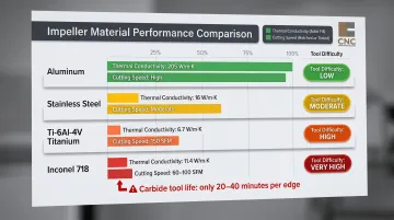
Nickel-based superalloys (Inconel 718) — The hardest common impeller material to machine. According to Criterion Precision's machining guide, Inconel 718 scores 12% on the AISI Machinability Index with carbide tool life of only 20-40 minutes and milling cutting speeds of 60-100 SFM. Material data from ASM/MatWeb shows thermal conductivity of 11.4 W/m-K. Work-hardened zones can reach 400+ Brinell hardness; white layers can reach 2.2 times the base material hardness.
| Material | Thermal Conductivity | Cutting Speed (Milling, Carbide) | Tool Life Challenge |
|---|---|---|---|
| Aluminum | ~205 W/m-K | High (standard rates) | Low |
| Stainless Steel | ~16 W/m-K | Moderate | Moderate (chip welding, work hardening) |
| Ti-6Al-4V | 6.7 W/m-K | 150 SFM | High (heat concentration) |
| Inconel 718 | 11.4 W/m-K | 60-100 SFM | Very high (20-40 min) |
Tolerances and Surface Finish
Precision impellers require tight control:
- Blade profile contour tolerance: ±0.05 mm for precision applications; ±0.01 mm for high-precision applications
- Bore concentricity: 0.005-0.01 mm
- Face runout: 0.005-0.01 mm
- API 610 rated duty head tolerance: ±3%
Flow channel surface finish targets:
| Manufacturing Method | Ra Value |
|---|---|
| Sand casting | Ra 6-12 μm |
| Investment casting | Ra 1.5-3 μm |
| CNC-machined flow channels (precision) | Ra 0.8-1.6 μm |
Source: Amarinth Manufacturing Tolerances
CNC-machined impellers deliver a 4-15x surface finish improvement over cast equivalents. Investment casting provides greater repeatability but costs 4 to 10 times more than sand casting for custom parts.
Post-machining surface conditioning — bead blasting, vibratory deburring, or anodizing — is often required to bring flow surfaces to hydraulic performance spec, particularly for impellers running in high-head or corrosive service conditions.
Common Problems and How to Avoid Them
Hitting those tolerances is straightforward in theory — in practice, a handful of recurring problems derail most impeller programs. Here's what to watch for.
1. Blade Surface Distortion from Excessive Cutting Forces
Cause: Improper roughing sequencing or excessive stock left for finishing creates uneven engagement on thin blade sections.
Solution:
- Use staged semi-finishing with controlled step-down
- Implement variable feed rates based on blade thickness
- Reduce stock allowance uniformly to prevent localized overload
2. Inconsistent Blade-to-Blade Surface Finish
Cause: Vibration from long tool overhang, tool wear progression across multiple blades, or toolpath discontinuities between passes.
Solution:
- Use continuous 5-axis toolpaths without dwell or retract marks
- Reduce tool overhang by optimizing axis orientation
- Maintain consistent cutter engagement throughout the blade family
- Monitor tool wear and replace before finish quality degrades
3. Hub/Bore Misalignment from Multiple Setup Errors
Cause: Repositioning operations between roughing, blade finishing, and bore finishing introduce cumulative alignment error.
Solution:
- Consolidate operations into a single 5-axis setup
- Perform bore finishing only after blade geometry is fully stabilized
- If a second setup is unavoidable, use datum features on the part — not the fixture — for subsequent operations
Frequently Asked Questions
What is the difference between 3+2 and full 5-axis?
3+2 (positional 5-axis) locks the rotary axes in place and uses 3-axis toolpaths from a fixed orientation—offering rigidity but limited reach. Full simultaneous 5-axis continuously moves all five axes together, enabling smooth surface tracking, better access to complex geometry, and superior finish on impeller blades.
What are the two types of impellers?
Impellers are broadly classified as open (blades exposed on one side) and closed (blades fully enclosed by front and rear shrouds — the most demanding to machine). Semi-open designs with a partial shroud fall between the two and appear frequently in pump and compressor applications.
What materials are most commonly used for impeller machining?
The most common materials are aluminum, stainless steel, titanium, and nickel superalloys such as Inconel. Each requires different cutting parameters and toolpath strategies based on machinability, thermal conductivity, and work hardening behavior.
What surface finish is required for impeller flow channels?
Hydraulic flow surfaces typically require Ra 0.8-1.6 μm. High-performance aerospace or compressor impellers often demand Ra 0.4 μm or lower, as surface roughness directly affects flow efficiency and cavitation behavior.
Can impellers be machined without full 5-axis simultaneous motion?
While 3+2 indexing can rough some material, it cannot reliably produce the blade form accuracy, surface continuity, and balance consistency required for precision impellers. Closed designs in particular cannot be properly finished without full simultaneous 5-axis motion.
What tooling is recommended for finishing impeller blades?
Tapered ballnose cutters are the standard choice for blade finishing due to their rigidity at extended reach. Tool selection should always prioritize the shortest tool that can reach the blade surface to minimize deflection and chatter.
Impeller machining is a geometry control problem at every stage. 5-axis simultaneous motion, CAM strategy, and collision-aware toolpath generation are baseline requirements — not optional steps — for parts that meet tolerance, surface finish, and balance specs. The core principles hold across materials: preserve concentricity through setup consolidation, control blade geometry through continuous 5-axis motion, and validate collision avoidance before any program reaches the machine.
For 5-axis CNC programming services covering impellers and other complex geometries, contact CNC Programming Solutions at 405-714-3714 or cncsolutions22@gmail.com.