Introduction: What Is Aerospace CNC Machining Fixturing and Why Does It Matter?
In aerospace manufacturing, fixturing — securing a workpiece during CNC machining — carries consequences no other industry matches. Landing gear, turbine housings, and engine mounts support life-sustaining systems. Dimensional failure on these parts isn't a quality escape. It's a safety event.
Machining engineers and programmers working on aerospace jobs frequently underestimate fixturing complexity. The result: scrapped parts, missed tolerances, and costly re-setups on materials like titanium or Inconel where a single billet runs hundreds to thousands of dollars.
Part movement is one of the most common causes of dimensional inaccuracy, surface defects, tool breakage, and job failure — which makes fixturing a critical control point, not an afterthought.
This guide covers the complete fixturing landscape for aerospace CNC machining:
- Fixture types — from modular plates to zero-point systems
- Advanced techniques like picture framing for multi-sided parts
- Design considerations for thin-wall and exotic-material components
- How fixturing integrates with CNC programming and AS9100 compliance
Key Takeaways
- Aerospace fixturing must hold parts through multi-operation machining where even 0.001" movement causes rejection
- Major fixture types — modular plates, zero-point systems, vacuum fixtures, and custom soft jaws — each serve specific part geometries and tolerance requirements
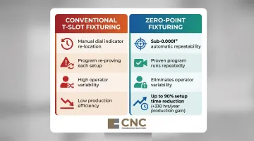
- Zero-point fixturing delivers sub-0.0002" repeatability and reduces setup time by up to 90%
- Fixture design must account for material behavior under clamping forces, especially titanium deflection and thin aluminum walls
- Datum setup, work offsets, and inspection repeatability under AS9100 all depend on how fixturing decisions are made
Why Fixturing Is More Critical in Aerospace Than Other Industries
Aerospace parts belong to life-sustaining systems where dimensional failure has catastrophic consequences. FAA regulation 14 CFR Part 21.137(d) requires production certificate holders to maintain "manufacturing process control procedures for controlling manufacturing processes to ensure that each product and article conforms to its approved design" — and fixturing is a controlled process element under this requirement.
Tolerances Leave No Room for Workpiece Movement
Aerospace parts routinely demand tolerances in the ±0.001" to ±0.0005" range. Requirements tighten further by system type:
- Engine components: ±0.0002" to ±0.0005"
- Fuel and hydraulic systems: ±0.0001" to ±0.0003"
Any workpiece movement between operations — even fractions of a thousandth of an inch — can push multiple features out of spec at once.
Multi-operation complexity makes this harder. Aerospace parts frequently require machined features on 3–5 faces, meaning parts must be repositioned multiple times during a single production sequence. Each repositioning introduces a potential datum shift. Reliable re-locating is the only way to maintain dimensional control across the full sequence.
Material Costs Make Fixturing Failures Expensive
The raw materials in aerospace machining are expensive enough that a single scrapped billet is a serious financial event. Titanium (Ti-6Al-4V) runs $3–$16 per pound; Inconel 718 costs $40–60/kg — 8–10 times the price of 316L stainless steel. Poor fixturing that causes a scrap event means hundreds to thousands of dollars in material loss, before counting machine time and labor.
Regulatory requirements extend that accountability further. AS9100 certification mandates that manufacturing processes — including fixturing setups — be documented, controlled, and repeatable. Lockheed Martin's FAI requirements explicitly state that tooling and manufacturing processes must appear in First Article Inspection documentation. Fixturing is part of the production approval process, not an afterthought.
Types of Aerospace CNC Machining Fixtures
Unlike general machining, aerospace fixtures are selected based on part geometry, number of operations, material properties, and tolerance requirements. There is no one-size-fits-all solution.
Modular Fixture Plates
Modular fixture plates use a grid of precisely spaced threaded holes or T-slots to allow flexible placement of clamps, stops, and locating pins. This is the workhorse of aerospace shops because one plate can be reconfigured for many different part shapes without building a new dedicated fixture each time. T-slot plates manufactured to DIN508 standards offer tolerances of ±0.05 mm per 150 mm, providing the precision baseline needed for aerospace work while significantly reducing tooling lead time.
Key advantages:
- One plate serves multiple part geometries
- Fast reconfiguration between jobs
- Lower tooling investment for low-to-medium volume runs
- Compatible with standard clamping hardware
Zero-Point Fixturing Systems
Zero-point fixturing uses a permanent base plate with precision-machined receiver pins installed in the machine table. Vises, fixtures, or pallets with matching locating shanks can be swapped in and out and automatically re-locate to within 0.0001" or less. Schunk VERO-S NSE3 with SPG40 clamping pins achieves <0.002 mm (<0.00008") repeat accuracy, while Erowa UPC delivers 2 µm repeatability with 50 kN clamping force.
This eliminates manual re-indicating between operations and reduces setup time for multi-op aerospace jobs. Both Jergens and ZeroClamp claim setup time reductions of up to 90% versus conventional T-slot methods, making high-mix aerospace production economically viable.
Critical specifications to verify:
- Repeatability (sub-0.002 mm for tight-tolerance work)
- Clamping force (typically 8–60 kN depending on part size)
- Service life (systems rated for 1,000,000+ cycles)
- Machine-to-CMM transferability (moving parts from machine to CMM without re-fixturing)
Vacuum Fixtures
Vacuum fixtures are particularly valuable for thin-walled aerospace panels, skins, and structural components (ribs, spars) that cannot be clamped mechanically without causing distortion. The vacuum distributes holding force evenly across the part surface, preventing deflection during cutting.
Pierson SmartVac 3 delivers approximately 14 lbs per square inch at 28 in Hg vacuum level, generating 504 lbs of holding force on a 6×6-inch part. That's adequate for many aluminum aerospace structural parts. Base accuracy of ±0.0025" and top plate repeatability of 0.001" keep the system within aerospace precision requirements.
Best applications:
- Thin-walled panels and skins
- Ribbed structural components
- Large-area parts with minimal wall thickness
- Parts sensitive to localized clamping stress
Custom Soft Jaws and Dedicated Fixtures
Custom soft jaws — typically aluminum or machinable material — are bored or milled to exactly match a part's profile, providing full surface contact and preventing localized clamping stress. Aerospace applications include turned components like shafts, bushings, and housings, as well as rotating workholding solutions for jet engine compressor blisks, turbine blades, and rotors.
Where soft jaws handle variety, dedicated hard fixtures address volume. Built for a single part number and geometry, they deliver setup repeatability across thousands of parts — with clamping locations and inspection access optimized for that specific component.
Key Aerospace Fixturing Techniques
Even with the right hardware, the technique used to fixture a part — how datum references are established, how parts are held through multiple operations, how nesting is arranged — has a major impact on accuracy, throughput, and scrap rate.
Zero-Point Fixturing Workflow: With vs. Without
| Without Zero-Point | With Zero-Point | |
|---|---|---|
| Part re-location | Manual dial indicator for every part | Sub-plate transfers with 0.0001" repeatability |
| Program re-proving | Required each setup; adds cycle time and operator variability | Proven once at first-article; runs repeatedly |
| Volume suitability | Impractical for high-volume aerospace runs | Scales efficiently across large orders |
Zero-point fixturing also extends into inspection. A matching base installed in the CMM department lets the vise and part transfer directly from the machine without any re-location time — the inspection program runs from the same datum immediately.
If a correction is needed, the part snaps back into the identical machine position, maintaining datum integrity throughout the entire process chain.
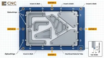
Picture Framing for Aerospace Panel and Structural Parts
Picture framing holds the workpiece billet within an outer frame of raw material using fasteners (such as Invert-A-Bolt) and locating pins (Zipbushings, retractable dowel pins). Rather than locating against the part's final datums (which may not yet be machined), the frame's locating features (not the part's datums) are referenced for all machining operations. This preserves datum relationships throughout the process.
Thin material tabs — over-the-top, along-the-flanges, or foil-thin bottom — keep the part rigidly connected to the frame until the final operation breaks them free. This also enables nesting of 10 to 20 parts within a single billet plate, increasing parts-per-hour output and reducing material waste.
When to use picture framing:
- Complex structural parts with features on multiple sides
- Parts where final datums are not available until later operations
- High-volume aerospace bracket and fitting production
- Multi-part nesting to maximize spindle utilization
Multi-Part Nesting and Continuous Machining
Aerospace shops running lower-cost aluminum structural components (brackets, seat tracks, access panels) often nest 6, 10, or even 20 parts per fixture setup to maximize spindle utilization. This strategy frees the operator to inspect completed parts or run adjacent machines during cycle time.
This approach is especially effective on horizontal machining centers where the rotary pallet allows multi-face machining in one setup. Picture framing enables the entire nested array to reference a single frame datum, eliminating the need to individually indicate each part location.
Material and Design Considerations for Aerospace Fixtures
Fixture material choice must match the demands of the workpiece material and process. Steel fixtures (SAE-AISI 4140) offer approximately 2.75x the rigidity of aluminum (6061-T6) per unit area, with elastic modulus of 190 GPa vs. 69 GPa, making steel preferred for heavy-duty cuts in titanium or Inconel. Aluminum fixtures are easier to machine and modify, but exhibit nearly double the thermal expansion (24 µm/m-K vs. 13 µm/m-K) — a critical consideration for precision applications.
For certain thin-wall or composite parts, soft materials like nylon or machinable plastic prevent surface damage while providing adequate holding force for light machining operations.
Clamping force and location require careful engineering around aerospace part geometry. Placing clamps too close to a thin wall or unsupported span causes deflection and out-of-tolerance surfaces. Designers should:
- Place locators and clamps at structural nodes
- Use support pins under thin sections
- Verify deflection analytically before running the first part
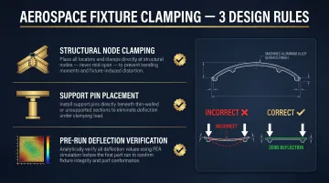
A peer-reviewed study on Ti-6Al-4V thin-wall machining demonstrated that hybrid FEA/statistical models achieved 80.3% to 99.9% agreement with experimental deflection data, reducing analysis time from weeks to hours. Integrating FEA into fixture design workflows for thin-wall components prevents costly scrap and rework.
Multi-Axis Access in Fixture Design
For 5-axis aerospace parts, every required machined face must be accessible to the spindle without the fixture body blocking the tool path or trunnion rotation. Low-profile fixturing, tombstones, and angled sub-plates are common solutions.
This design step must happen in parallel with CNC program development — not after. The fixture geometry directly constrains the tool path strategy, particularly for aerospace structures and turbine blades where compound angles and undercuts demand coordinated planning from the start.
Fixturing's Impact on CNC Programming and Quality Compliance
The work coordinate system (WCS) origin in the CNC program must precisely match the physical datum established by the fixture. In zero-point or modular fixturing, the datum is repeatable from part to part, which means the program can be re-used without re-proving. But any fixture redesign requires the programmer to verify or update WCS offsets.
Fixturing and programming must be developed together — not sequentially. G54-G59 work offsets in Fanuc-compatible controls define the relationship between the machine coordinate system and the workpiece datum. The fixture establishes the physical datum surfaces that correspond to the programmed WCS origin.
In multi-axis machining, fixture datum accuracy directly determines WCS accuracy. Any datum shift propagates as a systematic error through all programmed tool paths.
AS9100 Documentation and FAI Requirements
AS9102 Form 3, Field 10 requires recording designed/qualified tooling identification numbers and revision levels when specially designed tooling is used for inspection. A Partial/Delta FAI is triggered by a "change in tooling" — meaning fixture modifications require re-validation and documentation updates.
Aerospace shops must maintain:
- Fixture design records
- Inspection records for fixture accuracy (CMM verification of locating features)
- Traceability linking each fixture to the parts produced with it
Fixturing is part of the manufacturing process plan and must be reviewed and approved as part of the FAI process.
Designing for Inspection Access
Features that are difficult to access with a CMM probe or laser scanner due to fixture obstruction must be addressed at the design stage — not during inspection. Designing fixtures with inspection access in mind, or using zero-point transfer to CMM, reduces bottlenecks and ensures all critical dimensions can be verified without removing and re-locating the part. Digital Inspection Setup Sheets for CMM/PCMM must document part datums and may include inspection fixtures or tooling and clamping locations.
Frequently Asked Questions
What is the difference between a fixture and a jig in aerospace CNC machining?
A fixture holds the workpiece securely in place during machining while a jig guides the cutting or drilling tool itself. In modern CNC aerospace machining, fixtures are dominant since CNC control provides tool guidance, whereas jigs are more common in manual or older operations.
What is zero-point fixturing and why is it preferred for aerospace parts?
Zero-point fixturing uses a precision base plate with locating receivers so vises or sub-plates can be swapped between machines or operations with sub-0.001" repeatability, eliminating manual re-indicating. This makes multi-operation aerospace jobs both faster and more accurate while simplifying AS9100 documentation requirements.
How does fixturing affect CNC program setup for aerospace jobs?
The fixture's datum locating features define the CNC program's work coordinate system (WCS) origin. Repeatable fixtures let the same proven program run part after part without re-zeroing; a poorly located fixture forces the programmer to compensate or re-prove the setup each time.
What are the best fixture materials for aerospace CNC machining?
Material choice depends on the application:
- Steel — heavy-duty or high-tolerance fixtures requiring maximum rigidity
- Aluminum — lighter setups where machinability and reduced weight matter
- Soft/machinable materials — delicate thin-walled or composite parts where surface damage is a risk
Selection must match the thermal expansion characteristics and rigidity demands of the workpiece.
How do aerospace fixturing requirements differ from general CNC machining?
Aerospace demands higher repeatability (sub-0.001" re-location), full documentation and traceability under AS9100, fixture designs that consider CMM inspection access, and clamping strategies that account for expensive, difficult-to-machine materials where a scrapped part can cost thousands of dollars.
What is picture framing in aerospace machining and when is it used?
Picture framing holds an aerospace part within its surrounding billet material using fasteners and locating pins, referencing the frame rather than the part's own datums. It works best for complex structural parts with features on multiple sides and enables nesting of multiple parts per setup, increasing throughput and reducing material waste.