Introduction
In aerospace manufacturing, a deviation smaller than the width of a human hair can trigger component failure, structural compromise, or catastrophic in-flight events. When a 2.4-thousandth-inch drilling defect led to a fan hub fracture on Delta Air Lines Flight 1288 in 1996—causing an uncontained engine failure that killed a passenger and injured several others—the NTSB investigation revealed a sobering truth: manufacturing dimensional process gaps in rotating components can produce fatal outcomes. The drilling damage extended approximately 0.024 inches into the material, but subsequent boring and honing removed only 0.010 inches—insufficient to eliminate the subsurface defect that initiated the fatigue crack.
That case isn't an outlier — it's a benchmark. Micron-tolerance machining isn't a premium service; it's the baseline standard that keeps aerospace systems functional and safe.
This guide covers:
- What micron-tolerance machining means in practice
- Why aerospace demands it above all other industries
- Which components require it and why
- The technologies and programming strategies that deliver it
- How compliance is measured and verified
Key Takeaways
- Micron-tolerance machining holds dimensional accuracy to ±0.001" (25 µm) or tighter—10x to 200x beyond standard manufacturing , depending on application
- Aerospace components like turbine blades, landing gear, and flight control actuators depend on it for safety and performance
- 5-axis CNC machining, precision grinding, EDM, and CMM inspection are core enabling technologies
- Thermal expansion, material behavior, and tool wear require active controls—thermal compensation, real-time monitoring, and precision fixturing
- AS9100D, NADCAP, and AS9102 compliance are non-negotiable for aerospace supply chain participation
What Is Micron-Tolerance Machining and Why Aerospace Demands It
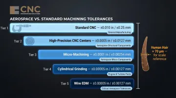
A micron—also called a micrometer—equals 0.001 mm or 0.00003937 inches. To visualize this scale, a human hair measures approximately 70 microns in diameter (ranging from 17 to 181 microns depending on individual variation). Aerospace tolerances commonly range from ±25 µm (±0.001") down to ±2.5 µm (±0.0001") for the most critical parts.
Aerospace vs. Standard Machining Tolerances:
Standard commercial CNC machining allows tolerances of ±0.010" (±0.25 mm) or looser. Aerospace precision machining tightens this by 10x to 200x:
- High-precision CNC centers: ±0.0005" (±0.013 mm)
- Micro-machining: ±0.0001" (±0.0025 mm)
- Cylindrical grinding: ±0.00005" (±0.00127 mm / 1.27 µm)
- Wire EDM: ±0.00005" (±0.001 mm)
Aerospace systems operate in conditions that leave no margin for dimensional error:
- Turbine inlet rotor gas temperatures: 2,500–3,000°F
- Blade tip speeds: approximately 1,500 feet per second
- Hydraulic system pressures: up to 3,000 psi
- Flight control loads: cyclic stress through thousands of landings
Why Tolerance Violations Matter
Dimensional deviations trigger failure across multiple systems:
- Stress fractures in high-load areas (landing gear, structural joints)
- Vibration-induced fatigue in engine rotating assemblies
- Fluid leaks in fuel and hydraulic systems
- System-level incompatibility during final assembly
The Delta 1288 case demonstrates the consequence chain: drilling damage → inadequate material removal → subsurface microstructure damage → fatigue crack initiation → catastrophic failure. Manufacturing process failures, not design failures, account for the majority of aerospace incident findings.
Regulatory and Quality Frameworks:
AS9100D (aerospace quality management system) and NADCAP (special process accreditation) are not optional — they're baseline requirements for supplying aerospace-grade components. AS9100D governs design controls, supplier oversight, nonconformance handling, and traceability down to the raw material used for each individual part.
NADCAP addresses special processes — grinding, EDM, heat treatment — where the process itself requires audit and approval, independent of the resulting dimensions. Both frameworks apply simultaneously; meeting one does not substitute for the other.
Aerospace Components That Require Micron-Level Precision
Turbine Engine Components
Compressor and turbine blades demand exact airfoil geometry for aerodynamic function and mass balance. NASA research establishes that each 0.010-inch of turbine tip clearance is worth approximately 1% specific fuel consumption (SFC) and 10°F of exhaust gas temperature margin. For large commercial fleets, improved tip clearances of 0.010 inches can produce fuel and maintenance savings worth hundreds of millions of dollars annually.
Surface finish is equally critical — rough surfaces create stress concentration points that initiate fatigue cracks under cyclic thermal and mechanical loads.
Landing Gear and Hydraulic Systems
Hydraulic cylinders, actuator rods, and pivot pins require precise bore and shaft diameters to prevent:
- Binding under load
- Hydraulic fluid leakage
- Fatigue cracking through repeated landing cycles
Even micron-scale misalignment accelerates wear at a rate disproportionate to the dimensional error. Landing gear overhauls — including non-destructive testing and hydraulic seal checks — routinely trace failure patterns back to original manufacturing tolerances.
Flight Control Actuators and Linkages
Ailerons, elevators, and rudder actuators all depend on tight tolerances for repeatable, predictable movement. Any dimensional play or geometric error reduces control authority and introduces unpredictability — particularly in high-maneuver scenarios where aerodynamic response must be immediate and exact.
Fuel System Components
Fuel injector orifices, pump internals, and valve seats govern atomization, flow rate, and combustion efficiency. Deviation from specified geometry directly affects:
- Emissions output
- Thrust consistency
- Overall fuel burn
Many injector orifices are machined via EDM drilling, with holes as small as 0.04 mm in diameter — tolerances where any variance is measurable in performance.
Fastener Systems and Threaded Interfaces
Bolts, rivets, and specialized aerospace fasteners must meet precise thread and shank tolerances to prevent loosening under vibration and maintain structural load transfer. Improper fastener fit is a common root cause in structural audits.
Key Technologies and Processes That Enable Micron-Tolerance Machining
Multi-Axis CNC Milling (4-Axis and 5-Axis)
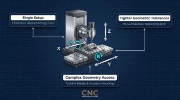
5-axis CNC machining is the cornerstone technology for complex aerospace geometries. It combines three linear axes (X, Y, Z) with two rotational axes (A, B), allowing simultaneous multi-axis movement that:
- Reduces repositioning errors by machining complex features in a single setup
- Maintains tighter geometric tolerances through elimination of cumulative positioning error
- Enables turbine blade profiles, complex brackets, and actuator housings in minimal setups
Each additional setup introduces potential misalignment. By accessing all surfaces in one setup, 5-axis machining eliminates re-fixturing errors that cause tolerance stack-up.
CNC Programming Solutions develops intricate CNC programs for 4-axis and multi-axis machines, supporting aerospace structures, turbine blades, and high-precision engine parts where setup reduction directly affects dimensional outcomes.
Precision CNC Grinding
Cylindrical and surface grinding with CNC grinders achieve tolerances as tight as 0.00005" (1.27 µm) for hardened steel aerospace components like hydraulic spools and valve sleeves. CNC grinders with thermal compensation and closed-loop feedback are essential for maintaining sub-micron tolerances across production runs.
Electrical Discharge Machining (EDM)
EDM—wire and sinker—machines hardened materials and geometries impossible to cut conventionally. It removes material through controlled electrical erosion, achieving tight tolerances on intricate internal features without mechanical cutting forces that could distort the part.
Aerospace EDM applications include:
- Turbine engine cooling holes in blades, vanes, discs, nozzles, and shrouds
- Diffuser shapes typically 0.060" × 0.032" and 0.040" deep
- Through holes as small as 0.020" diameter
- Wire EDM tolerances: ±0.00005" (±0.001 mm)
NADCAP classifies EDM under "Nonconventional Machining" alongside ECM, laser beam machining, and abrasive water jet, all of which require accreditation for aerospace supply chain participation.
Coordinate Measuring Machines (CMM) and In-Process Gauging
CMMs use touch-probe and laser scanning to verify dimensional accuracy to sub-micron levels. Touch-probe repeatability reaches 4 microns (0.004 mm) under B89 specification calibration.
In-process gauging—where measurements are taken during machining, not just after—enables real-time correction and prevents out-of-tolerance parts from completing a full cycle before errors are caught. Industry data shows that 70% of defect spikes trace to an equipment condition event within the prior 72 hours, supporting the value of upstream quality control over end-of-line inspection alone.
Environmental Controls
Those measurement systems only hold their accuracy if the environment around them is stable. Precision machining facilities must control ambient temperature to ±1°C or better. ISO 1:2016 defines the standard reference temperature for all industrial dimensional measurements at 20°C, a baseline adopted internationally since 1931.
Why temperature matters:
Ti-6Al-4V titanium has a coefficient of thermal expansion (CTE) of 8.6 µm/m-°C. That means a 300 mm titanium shaft expands roughly 2.6 µm for every 1°C of temperature rise — and when the target tolerance is ±2.5 µm, a 2°C ambient swing consumes the entire tolerance band.
Humidity and air quality control are additional variables affecting measurement accuracy and surface integrity.
CNC Programming Strategies for Achieving Micron Tolerances
The machine is only as precise as the program running it. Toolpath optimization—minimizing tool engagement angles, managing radial and axial depths of cut, selecting climb versus conventional milling—directly determines whether a part holds tolerance or drifts during cutting.
Climb Milling vs. Conventional Milling:
| Attribute | Climb Milling | Conventional Milling |
|---|---|---|
| Chip formation | Width starts at maximum, decreases | Width starts from zero, increases |
| Surface finish | Better—chips removed behind cutter | Worse—chips carried upward, risk of recutting |
| Tool deflection | Reduced—lower load on cutting edge | Higher—"cutter tends to dig into workpiece and may cause part to be cut out of tolerance" |
| Tool life | Improved | Reduced |
Climb milling is generally the best practice for aerospace precision work because it reduces cutting edge load, improves surface finish, and minimizes the dimensional drift caused by tool deflection.
Feed Rate, Spindle Speed, and Depth of Cut:
Programmers must tune parameters for the material and feature being machined. Aggressive settings generate heat and tool deflection; overly conservative ones extend cycle times and can still miss tolerance through cumulative tool wear. Finding the right balance requires:
- Matching feed rate and spindle speed to material hardness and tool geometry
- Limiting depth of cut on finishing passes to reduce deflection
- Monitoring tool wear intervals to catch dimensional drift before it compounds
CAM simulation tools such as Vericut validate toolpaths and predict deflection before a single chip is cut—catching errors that only reveal themselves under real cutting loads. This step significantly reduces scrap and rework on tight-tolerance aerospace features.
Expert programmers balance speed, accuracy, and tool life in ways that directly affect dimensional output. CNC Programming Solutions applies this discipline specifically in multi-axis programming, where compounded axis movement makes parameter decisions more consequential.
Fixture and Operation Sequencing:
How a part is held affects how it responds to cutting forces. Programming the sequence of operations to account for part deflection—roughing before finishing, leaving finishing allowances strategically—separates micron-capable shops from standard-tolerance operations.
Overcoming the Biggest Challenges in Micron-Tolerance Machining
Material Complexity
Titanium alloys:
- Springy and generate intense heat during cutting
- Low thermal conductivity means heat concentrates at the cutting edge
- Require specialized tooling geometry and coatings
Inconel (nickel superalloys):
- Work-harden rapidly, generating extreme heat at the tool-workpiece interface
- Accelerate tool wear dramatically
- Gall and form built-up edges, causing tolerance violations unless cutting parameters and coolant strategy are tightly controlled
Controlled machining studies show surface finish can degrade 2x (from 11-12 µin Ra to 25-26 µin Ra) and end-mill consumption can double when machining Inconel 718 without optimized coolant.
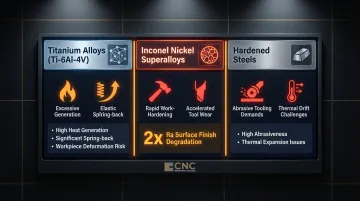
Hardened steels:
- Require specialized abrasive tooling (CBN or ceramic inserts)
- Prone to dimensional drift without consistent cutting parameters and thermal management
Thermal Expansion and Environmental Stability
Thermal expansion is one of the most underestimated sources of tolerance error. Shops must implement:
- Machine warm-up protocols
- Coolant temperature management
- Part stabilization periods before final inspection
- Adherence to the 20°C ISO 1:2016 reference temperature
Tool Wear and Dimensional Drift
Cutting tools gradually lose edge geometry, causing progressive dimensional drift. Flank wear directly determines diametric accuracy, machining stability, and run-to-run predictability.
Mitigation strategies:
- Tool wear monitoring systems
- Scheduled replacement intervals based on material volume cut (not just time)
- In-process gauging checkpoints to catch tolerance violations before they propagate across a batch
Two data points bear this out:
- Tools reach end-of-life 30-40% earlier than calendar-based schedules anticipate
- Defect rates spike 2.1x when spindle bearing lubrication is 10+ days overdue
Quality Inspection and Compliance Standards for Aerospace Parts
CMM Inspection and Metrology
CMM inspection verifies dimensional accuracy using touch-probe and laser scanning. Surface roughness profilometers measure finish; bore gauges verify internal features. All inspection data must be documented and traceable to serial numbers for AS9100D compliance—not just retained as aggregate pass/fail records.
AS9100D Quality Management System
AS9100D builds on ISO 9001:2015 with aerospace-specific additions:
- Risk management carried throughout all requirements
- Supplier control with additional purchasing oversight
- Configuration management for traceability of part numbers, process revisions, and raw materials
- Nonconformance handling with specific requirements for process and product action
- Traceability (Clause 8.5.2) requiring ability to trace all products from one material batch and their sequential manufacturing record
AS9100D is a prerequisite for NADCAP accreditation.
NADCAP Accreditation
Administered by the Performance Review Institute (PRI), NADCAP covers special processes where the process itself must be audited:
- Chemical processing (plating, anodizing, conversion coatings)
- Heat treating (stress relieving, annealing, carburizing, nitriding)
- Non-destructive testing (NDT)
- Nonconventional machining (EDM, ECM, laser beam machining, abrasive water jet)
- Welding (brazing, electron beam, laser, resistance)
First Article Inspection (FAI) per AS9102
AS9102 (current revision 9102B) standardizes FAI documentation. Key requirements:
- Three forms required: Part Number Accountability, Product Accountability (raw material, special processes, functional testing), Characteristic Accountability (dimensional/test results)
- Self-inspection prohibited: The person verifying characteristics cannot be the same person who generated them
- Equipment independence: Verification equipment must differ from production equipment
- Requalification triggers: 2-year production lapse, change in manufacturing source/process/location/tooling/materials, or change in inspection method
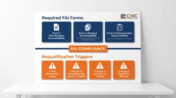
FAI requalification is an ongoing obligation, not a one-time milestone — any change in process, source, or materials restarts the clock.
Cost Impact:
These compliance requirements exist for measurable financial reasons. Aerospace cost of poor quality (COPQ) runs at 10-15% of total revenue, with industry scrap rate benchmarks at 2-3% for high-mix production.
In one documented case, linking maintenance logs with quality inspection records reduced scrap rate from 4.8% to 3.1% — a 35% improvement that saved $805K annually against a $2.3M scrap cost baseline.
Frequently Asked Questions
Frequently Asked Questions
What tolerance range is considered "micron-level" in aerospace machining?
Micron-level tolerances are generally ±0.001" (25 µm) or tighter. The most critical aerospace features—turbine tip clearances, fuel injector orifices, hydraulic actuator bores—may be controlled to ±2.5 µm or less using precision grinding and EDM processes.
Which aerospace components require the tightest machining tolerances?
Turbine blades, hydraulic actuator bores, fuel injector orifices, and flight control linkages most frequently call for sub-10 µm tolerances. These components combine extreme operating environments with functional requirements where dimensional precision directly affects safety and performance.
How does CNC programming directly impact tolerance accuracy?
Toolpath strategy, feed/speed parameters, and operation sequencing all affect cutting forces, heat generation, and tool deflection, each of which shifts actual dimensions away from nominal. Expert programming controls these variables through climb milling selection, optimized depth-of-cut, and sequencing that accounts for part deflection.
What materials are hardest to machine to micron tolerances?
Titanium alloys (Ti-6Al-4V) and nickel superalloys (Inconel 718) are the most challenging, driven by heat resistance, work-hardening, and spring-back during cutting. Holding tolerance on these materials requires specialized tooling, high-pressure coolant, and tightly controlled feeds and speeds.
What certifications govern micron-tolerance aerospace machining?
AS9100D (quality management system), NADCAP (special processes including EDM, grinding, heat treatment), and AS9102 (first article inspection) are the primary standards aerospace suppliers must meet. These are not optional—they're baseline requirements for supply chain participation.
How does shop temperature affect micron-tolerance machining outcomes?
Thermal expansion affects both the workpiece and machine structure. A 300 mm titanium shaft expands roughly 2.6 µm per 1°C rise—enough to consume the entire tolerance band at ±2.5 µm. Temperature-controlled environments (±1°C) and machine warm-up protocols are non-negotiable at this precision level.
CNC Programming Solutions provides precision CNC programming and multi-axis machining for aerospace and high-precision components. For project inquiries, contact us at 405-714-3714 or cncsolutions22@gmail.com.